Vilros Microbit Breakout Board.fzpz (21.1 KB)
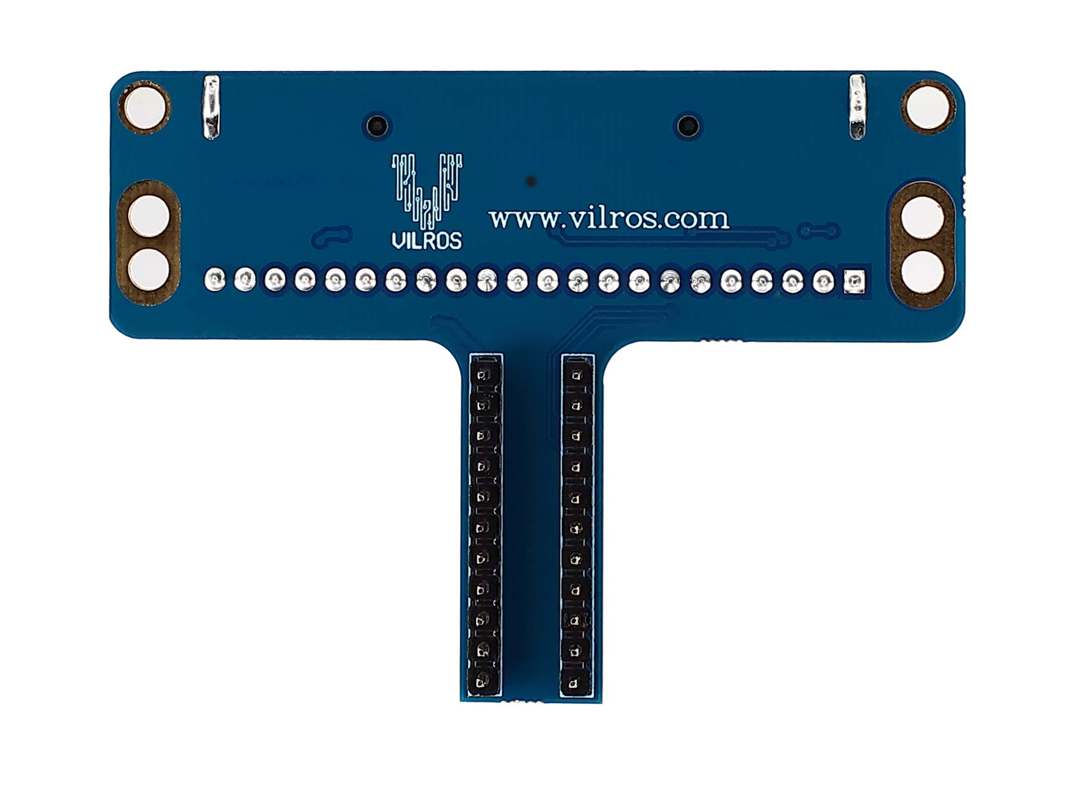
Is there a web page with a pinout of this device? A google search doesn’t find one and it appears breadboard and pcb are quite different which is unusual. For instance there are 22 pins (I think corresponding to the 22 pins on the breakout) in breadboard but not on pcb.
Peter
Hello,
Are you looking for a pinout of the microbit or a pinout of the brekaout board.
Microbit pinout:
https://os.mbed.com/platforms/Microbit/

Yes, thanks! With that I can improve your part a bit I expect. The two side connectors for power and ground should appear in breadboard (but don’t appear to) and the strip of I/O connectors should appear in pcb (although they probably aren’t too useful unless you unsolder the connector) and the I/O connector probably shouldn’t. I see both Fritzing parts for the board itself are incomplete as well (neither has more than breadboard) so I may make a better part there too.
Peter
sorry i think i misunderstood your question
No, the images are what I wanted, your current part is scaled a bit wrong and has some connector issues, so I’m going to modify it to be a better part. After that it may be worthwhile to make a proper Micro:bit part because there doesn’t seem to be one and it is a good fit for Fritzing (which may in turn attract more people to Fritzing). The last image is useful as that indicates how pcb should change (the Micro:bit connector removed and the 22 pin header added) to be able to use this part on a PCB if desired i.e you could solder this to a PCB and plug the Micro:bit in to it. Do you know if there are eagle files available for this board? If they are Eagle2Fritzing will make the necessary svgs with the pins in the correct places (at present I’m rescaling the png file to fit a 22 pin header to get the sizes which won’t be quite exact).
Peter
OK here is a perhaps improved version of your part along with some things to check
Vilros Microbit Breakout Board-imporved.fzpz (22.3 KB)
Since I don’t see this on the Vilros web site I’m assuming this may be a new product not released yet. My breadboard is much the same, except I lightened the background a bit to provide more contrast and added a male 22 pin header to the top connector. I scaled the png image til the .1 connectors aligned and used that for the outline, you probably want to print out both breadboard and pcb at 1 to 1 scale and compare it to a real board to make sure the dimensions are correct (especially on pcb). Schematic is changed a lot, as I prefer them to match the breadboard layout as I find that more convenient when debugging and I think it makes it easier for new comers to understand. However a group of educators I was helping to fix up the Calliope board decided a conventional schematic was better for education than one that matched breadboard. Which ever you like is fine. Pcb also has a lot of changes, it looks like it may have had an earlier rev of the board as a base, because it didn’t match the images above. I eliminated the micro:bit connector and added the 22 pin header and the two power terminals, but the position and size of the mounting holes likely need adjusting to match a real board. I suspect not many people will be using the pcb section of this (a connector for the Micro:bit is a more likely choice) but if someone wants to this should do the job, Internally (in the fzp file) I renumbered so the pins are in sequence and the labels on the pins match the pinout diagram on the micro:bit web site. If the pins are not in sequence Fritzing assumes they are (perhaps for caching reasons, I haven’t yet looked at the code) and will issue wrong pin labels when you hover over a pin if they aren’t in sequence. I’d guess this part came from eagle2fritzing as the pin layout looked like that (as well as the internal labeling). As well if you want this to be included in core parts, you need to make a pull request against the github repository. At least for the last couple of years (and despite what several things say) just posting it here won’t get it in to core parts. Hope this helps.
Edit: An additional improvement (this one is a new part so it will load beside the original one above), the difference in this part is that I copied a Micro:bit board in to connect to the connector as it would in real life. The original part is useful when you only want the adapter without the Micro:bit, but most folks are going to be using it with a Micro:bit installed and will likely prefer this part as it looks like real life.
Caytan Enterprise Micro bit Tail with Microbit.fzpz (44.5 KB)
Peter