I’m still studying things. I have found in the gerberexport how it deals with drill holes so now if I can figure out how to use that data in the trace clipping function we would be set.
Wow! 
Many thanks for extra-fast (and “magic” for me!!!) resolution of this problem! 
Is the src/items/clipablewire.cpp modification replicable on a current installation (it’s a script I can change on my pc), or I must wait for a new full build of Fritzing?
Love open source and his communities!
Unfortunately it has to be compiled and built so It is not a change you can make on your current running system. This does mean having to wait for the next release.
Well… ok… Thanks ![]()
Ideas about deadline for next release?
Or I can try to patch https://github.com/fritzing/fritzing-app/archive/0.9.3b.tar.gz and compile… ![]()
![]()
If you patch that exact copy of Fritzing and compile it you would be best off. As it stands development has stalled and there are a few of us trying to get it going again but that means it could be a long time before another release. Also the current development version has a lot of bugs so you must use the source you linked to not the Github repo.
If you are a linux user I could provide a working compiled copy of Fritzing with the patch. If you are a Windows or Mac user you will have to figure it out on your own because I do not have a system to compile it against. If you do end up compiling it on one of those systems I am sure everyone would be happy if you shared your success and your experience.
Hi Sublimeartistry,
I read above that you wanted the circuits to not go to the center of the pads (clipping). This is wrong in my opinion as all traces should begin and end in the center of a pad (common DRC practices). I also don’t understand why the pads are always donuts and not solid. it that a software option?
I have spent a lot of time fixing Gerbers from customer that had these types of donuts instead of solid pad. If this software provides an IPC-365 Netlist then these holes will be a problem based on my experience. I do understand that visually some people might want to see the holes in the pads to represent the drills but I am use to just turning on the drill layer when I want to see the whole picture.
Hopefully I am not too off track on this posting…
Respectfully,
DiodeDave
@DiodeDave It is not that I want the path clipped but rather that a lot of users of Fritzing are makers and a lot of makers do home etching and they want a nice round hole in the SVG and/or PDF output to center their drill. For those cases we should be doing a difference of the drill SVG from the Copper SVG giving them exactly what they want.
As for the gerber output it is good to hear that solid disks are preferable to rings. But the reason for the rings is how Fritzing works for parts creation. We create an SVG image with rings and Fritzing calculates the hole diameter you want from the SVG and then uses the SVG image as the copper component. It should not be hard to discard the inner SVG data for the rings to create a solid but again that would require someone more familiar with Object Oriented Programming than me.
The actual bug here is the result of the math being done inside a function and the same math being done to the data before sending it to the function. So my patch was to simply remove the math being done before the function and just leaving it in the function itself.
As for netlists we can currently export them in XML and SPICE but I do not know the compliance ratings for them.
@5volts I have reverted the changes making the current development version unusable and created a branch for it https://github.com/Intrinsically-Sublime/fritzing-app/tree/Testing it has the patch for this issue plus all the other small bug fixes that have been committed in the last year but without the bug that has been preventing a new version. You will still need to compile it yourself unless you are a Linux user in which case let me know and I can share the 64bit Linux Binary.
1 Like
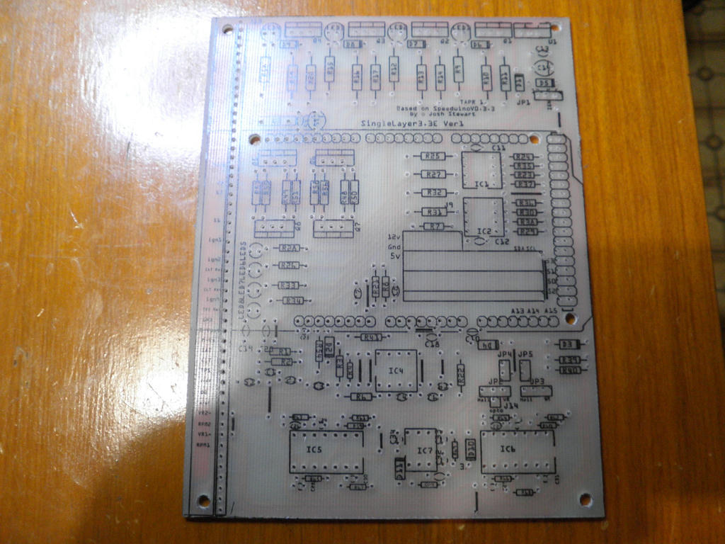
I don’t think I could home etch with the center missing. I would need to center punch 100s of pads to guide the drill, and that would have to be inaccurately by eye. Even now the std 0.040" center isn’t accurate enough, so I put a 0.004" via on all of them.
This was done with 0.040" center holes, but If you look at the bottom row of holes on IC4 you can see what no center hole guide does.
That is why I said.
This would mean it could have no hole up until export to SVG or PDF where it could then make the holes with a difference operation.
I’ve just discovered that I think this isn’t always true. My parts check script complains that
Error 74: File
‘/cygdrive/c/fritzing/fritzing.0.9.3b.64.pc/fritzing-parts/core/…/svg/core/pcb/DRV8825_breakout_pcb.svg’
At line 26
Connector connector146 has no radius no hole will be generated
Which isn’t really true (although I’m not planning on trying to fix it ![]() ). The connector is in fact a path rather than the usual circle with a stroke width. Somehow Fritzing figures this out and creates a correct hole and pad in the gerber (at least it did in another case that I looked so I assume, without having checked, that it does here too). It may be that it is finding the equivalent of a hole diameter and a stroke width in the path (I know very little about paths) but it is obviously more capable than just a circle and a stroke width which is all that I thought it dealt with. For my purposes this is odd enough (there are only a couple of cases in all of the core parts) that I’m going to leave it as an error that can be ignored if the user is sure its ok.
). The connector is in fact a path rather than the usual circle with a stroke width. Somehow Fritzing figures this out and creates a correct hole and pad in the gerber (at least it did in another case that I looked so I assume, without having checked, that it does here too). It may be that it is finding the equivalent of a hole diameter and a stroke width in the path (I know very little about paths) but it is obviously more capable than just a circle and a stroke width which is all that I thought it dealt with. For my purposes this is odd enough (there are only a couple of cases in all of the core parts) that I’m going to leave it as an error that can be ignored if the user is sure its ok.
Peter
@vanepp I believe Fritzing makes anything yellow in the copper group copper. Then it looks for any radius in the copper group and makes them holes. At least this is how you can make a non-round pad with a round hole. You just put a circle without a stroke wherever you want the hole. I usually make it solid black so I can see the hole.
Maybe it doesn’t entirely know because I remember I guy having problems with paths for connectors so we told him to switch to circle, and that fixed it. Seams like a lottery, unless we can find the circumstances.
I have created a pull request on the main Fritzing repo to have this fixed. Start trace at center of connection point by Intrinsically-Sublime · Pull Request #3379 · fritzing/fritzing-app · GitHub
That may have been me. I had created a part from an SVG I generated from an image and the holes were tiny in the Gerber export. It turned out to be the result of not having a radius defined and since my part was set as a through hole part in Fritzing it did make holes but it didn’t know how big to make them. The solution as we found was to replace the polygons with proper circles.
Hi to all!
Is this bug fixed in 0.9.4/5 in-progress release?
tks!
Yes it solved in the current development branch, which will become 0.9.5
Kjell: does the distribution system generate regular binaries for the dev versions? If not could it easily do so, on a nightly or weekly basis that would be available on github? I’d like to run the cutting edge dev version to find bugs early and benefit from the fixes both.
Peter
Thanks @KjellM
+1 support to @vanepp proposal of an easy way for test new dev-releases, also for people not dev-skilled.
Can I suggest to open a specific forum thread with news about development? Just for have more visibility and hype about new version and for work of our great devs!
I have the same problem. My teporairly solution is change to small thickness make and move with any point on trace and delete them. Then change the thickness back to origin wanted. Much work up during optimising of PCB. 
Please open an issue for a bug report on github here
as this is supposed to be fixed in Fritzing 0.9.6 and if it isn’t then it needs to be looked at. Are you running Fritzing 0.9.6?
Peter
In 0.9.6 all O.K. Thank You.