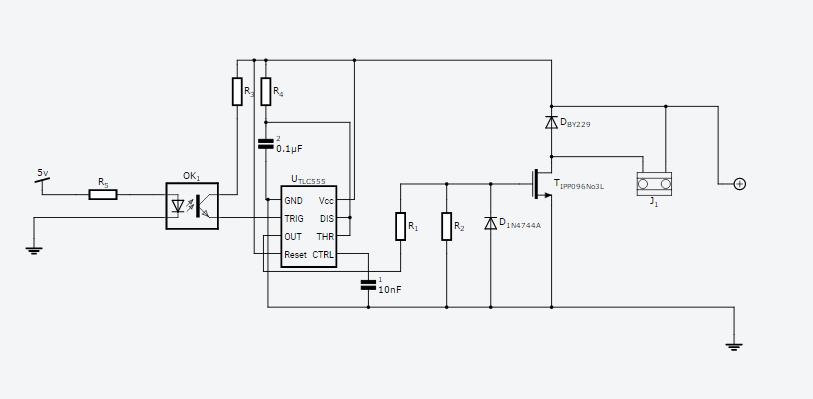
I’m trying to use a microcontroller to activate an optocoupler connected to 555 timer which is connected to a MOSFET. The circuit will drive a solenoid which draws 2amps at 12v. I’m new to circuit design but have combined a few schematics I have found to come up with the one below. I think I have some resistor values wrong, and I’m unsure if the 555 can drive the MOSFET directly???
5ms pulse fom micro converted to .5 second pulse by monostable 555
Solenoid is 130ft. of 30AWG magnet wire. 13.4 Ohms
The solenoid in this circuit is coupled with another solenoid, connected to an identical circuit as this one, except their polarity is reversed. So one circuit magnetizes the core in one direction and the other circuit magnetizes it in the reverse. Since they are coupled, one circuit will create current in the other right? Does that cause any problems, or will it be shunted by the diode (BY229)?
Another thing I was thinking about is having an H bridge connected to the 555 and using the same solenoid, instead of having two. I’m trying to keep the cost down as I need a number of these circuits, and an H bridge design seems to be more expensive from what I can find. Thanks
For reference, I’ve found some article about optocoupler,MOSFET and microcontrollers in an electronic blog named kynix electronic blog. You can have a read if you need.
Off the top of my head without doing detailed calculations here is what I see (and what I think you should do): The mosfet looks fine as it is fed by a 12V source is high current and has a logic level (~2V) gate threshold. The data sheet I read doesn’t seem to have a max source gate voltage but did show operation at 10V so the r1/r2 voltage divider should do the job to keep that in range (it will be somewhere in the 10 volt range I expect). The 555 should drive it fine. You can verify that by breadboarding your circuit (on a real breadboard with real parts) and start by using a wire on the end of R1 that should go to the output pin of the 555 and connect that to ground (which should turn the solenoid off) and then 12v (which should turn the solenoid on.) Once that works then you can go on to debugging the 555 part (where I think you are correct you have wrong resistor values). I’d start at the optocoupler which I think (hope?) is missing a ground and power connection. I’d expect there to be a connection to the optocoupler module to ground and +12V on the 555 side of the circuit (which may be present but not shown). In the data sheet at http://www.leg-gmbh.de/en/OK1-en.pdf I think the 24 volts wants to go to your +12V supply and ground to -12V (ground) and the output with no pull up resistor r3 (although it won’t hurt anything) going to the trigger pin of the 555. The ok1 output will switch between 0 and 12 v which will trigger the 555 fine. I think you main problem is that r4 and C2 (or 2 as it is in the drawing) are too small. Those two are what set the output time constant and if you need .5 second I’d expect both to be much larger. There are lots of tutorials on the net on the 555 timer and setting its output time constant and probably calculators for the values so check one of those to see if your values are indeed correct (they may be and I’m incorrect ). Otherwise I think this shoud work. If cost is a consideration, something else to consider is changing the software in the micro (which may not be possible) to output the .5 second pulse and eliminate the 555, just drive the Mosfet from the optocoupler output.
 ). Otherwise I think this shoud work. If cost is a consideration, something else to consider is changing the software in the micro (which may not be possible) to output the .5 second pulse and eliminate the 555, just drive the Mosfet from the optocoupler output.