Hello Forum, I hope my work is useful for someone.
TM1638_Led_and_Key.fzpz (23.1 KB)
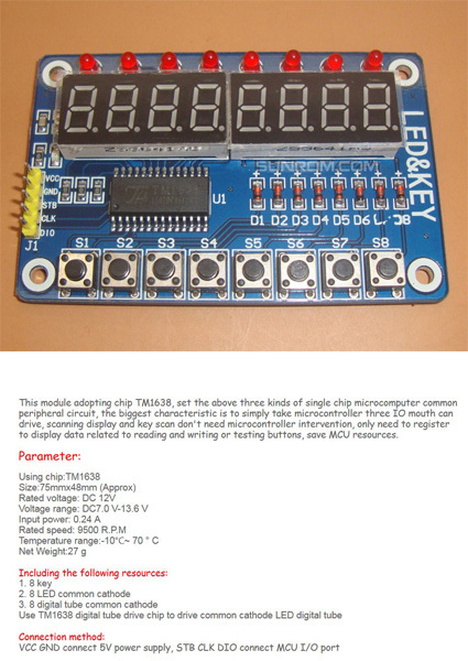
This looks like a common part.
Slight point on the Breadboard view. Great drawing, and the board pins line up with the BB holes perfectly - I see a lot of misalignment with 1st timers -, and this is only a slight thing that is not supper essential, but usually when you drag a shield on the BB the pins usually contact the BB and the rows light up green. Rotate it 90º and put it on the BB.
In the PCB view the silkscreen is missing.
Good work so far.
Hello Old_Grey,
thank you very much for your kindly comments.
The three parts were my first contact with Fritzing and I used them only for the description of a project - it is my first project with an Arduino. I try to work after the instructions but I know it is not perfekt. But I hope my work is useful for someone who knows the complete rules and can improve it.
Best regards
Thomas_W59
It took me 3 months to make my first totally new part, simply because there were no instructions and no help. I had to reverse engineer it by looking at other parts and use trial and error to work it out. I taught other guys what I knew, and they worked out other bits that I missed and taught other guys, and now we kind-of know what we are doing.
In the XML structure of the PCB view - I use the XML Editor in Inkscape - you just have to add a node above copper and call it silkscreen. And in that you add a rectangle representing the outline of the board - the rectangle has to be accurately positioned in relation to the contacts because this is a simple engineering drawing fit for production.
Then just add the 4 accurately positioned mounting holes/circles into copper.
I’m not a BB expert so I don’t know why the contacts don’t mate with the board - probably missing some XML nodes -, so I would have to reverse engineer it from other parts.