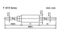
I’m looking for a part which resembles closely the PCB requirements of a thermal fuse type SF70E. It has a 1mm lead thickness. Anyone having it available or could direct me to a similar PCB part?
Rgds
Dick
In the meantime I found the attached file. However, it does not appear to load properly. Can anyone identify what’s wrong?Thermal Fuse 73°C.fzpz (10.2 KB)
Try this one. Swiped pads from the 1n4001 diode to get .042 holes (the lead on yours is ,039), the schematic from a fuse, edited the diode breadboard some what to move the spacing to .6 (the body of the fuse is .43 so .5 seemed a little tight) removed the anode band and changed the color from black to silver and moved pcb from .3 to .6 spacing.
Edit: The one you found has odd characters in the file names that appear to be throwing Fritzing. It however has a much better breadboard view so I swiped it. You may need to check my lead spacing as he or she used .4 spacing (and .035 holes) which doesn’t seem to match the data sheet but I don’t have one and whoever made the part may have. I have replaced the part below with a new one.
non-restable_thermal_fuse.fzpz (8.5 KB)
Peter
Hi Peter, this is absolutely perfect. Would it also be possible to upgrade the pin holes of the attached Sparkfun Varistor V18za2p pin holes to 1mm? I’m using the Littlefuse LA Series Metal Oxide Varistor 1nF 100A, Clamping 620V, Varistor 354 → 413V which is having the same pin distance but the leads are 1mm. If you could name it VA250LA40BP it would be absolutely great.
sparkfun-discretesemi-v18za2p-.fzp (1.9 KB)
Rgds
Dick
Sure, trivial change. I see breadboard is .2 spacing but pcb is .3 so I left it like that. You may want to check the part and see which is correct.
VA250LA40BP.fzpz (6.5 KB)
Peter
Hi Peter,
thanks a lot. It would suggest from the PCB view that the pin holes are less than 1 mm which is the varistor lead thickness. At least if I compare it in PCB view with the non-resetable_thermal_fuse you prepared earlier. I also noticed that in breadboard view, the connection does not take place at the end of the leads but at the varistor itself where the lead enters the varistor. Am I correct in this?
Rgds
Dick
The gerber output is .042 in (and 1mm is .039) so the holes should be correct. I didn’t change anything in breadboard so the pins being off is in the original Sparkfun part. I can correct that if you like. The part shows .2in lead spacing in breadboard but .3 in in pcb and I don’t see a VA250LA40BP at littlefuse (and they look to have both .2in and .3in spacing depending on the part.
Peter
This is the spec sheet I’m looking at:
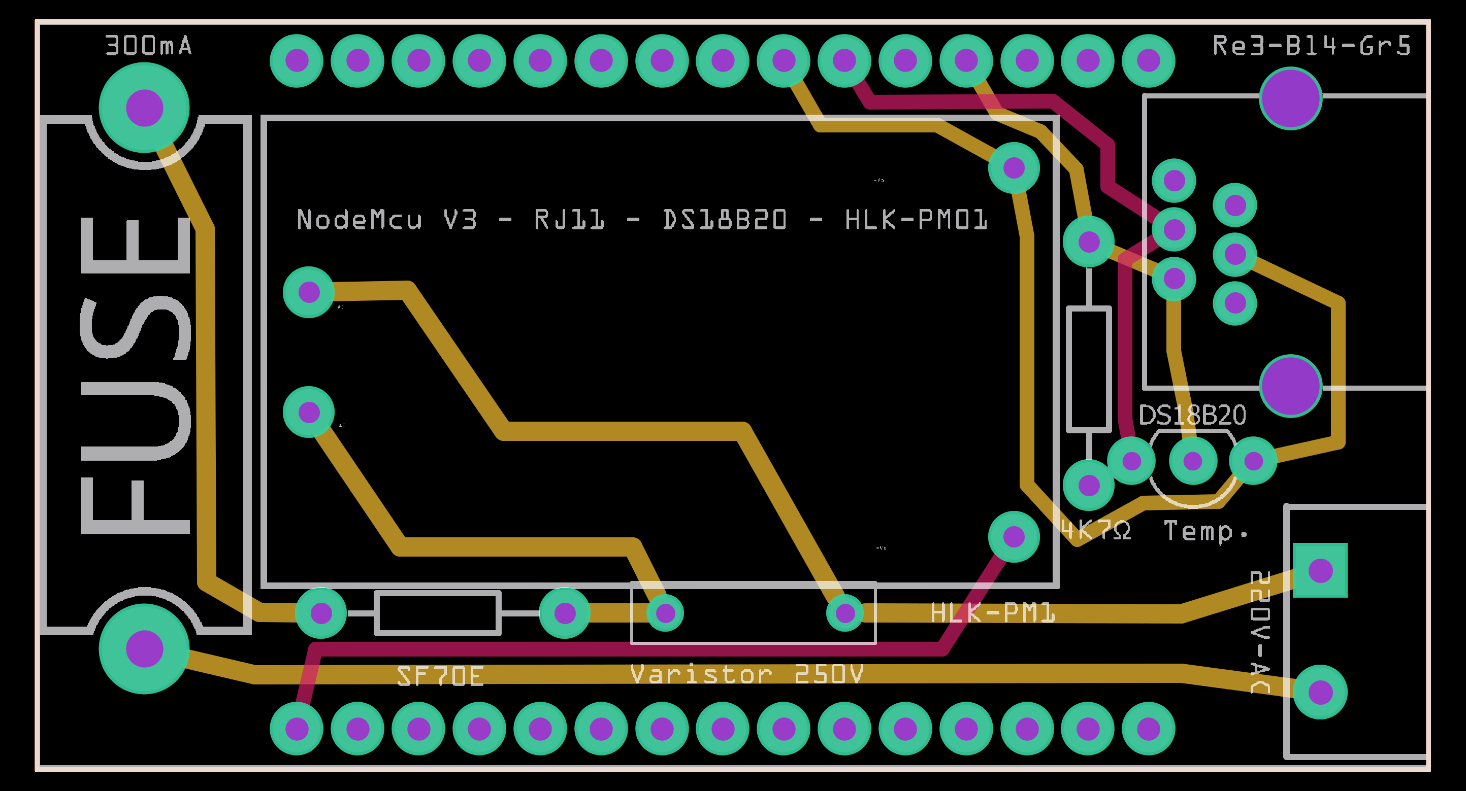
http://www.farnell.com/datasheets/2243464.pdf?_ga=2.202696017.1904644888.1500409158-1610208532.1498828716I also attached a Gerber output where the pin holes (Varistor 250V) show different dia than for the thermal fuse (SF70E) which also has 1 mm leads.
Where am I wrong?
Rgds
Dick
I expect the pad surround is greater on the fuse, if you look at the drill file
(Untitled Sketch_drill.txt in my case) it should say:
; NON-PLATED HOLES START AT T1
; THROUGH (PLATED) HOLES START AT T100
M48
INCH
T100C0.042000
%
T100
X018224Y014222
X015222Y014222
T00
M30
for both holes (the line T100C0.042000 indicating that the hole is .042 inches). That doesn’t affect the size of the pad which looks to be greater for the fuse. The purple part in the center is the hole size which should be the same. The data sheet listed is the one I was looking at. There isn’t (that I can see) a part VA250LA40BP there is a V250LA40BP which says it is a 20mm part which has a lead spacing from 6.5 to 8.5mm where .3in (the current pad spacing) is 7.62 mm which should fit fine (meaning breadboard on the part is incorrect). .I can fix up breadboard easily if you like.
Peter
Hi Peter, Got you! You are correct, it’s the V250LA40BP! It’s indeed the soldering? ring (pad surround) which makes the difference with the thermal fuse with the hole indeed the same, i.e. .042 inches. For my info, what determines/sets the pad surround, is that not a default value? Components are both connected to a 32mil pcb layer track.
The part has a 6.5 - 8.5 lead spacing. Appreciate if you could update the breadboard view. Would it be possible you concurrently rectify the lead snap, now at the junction of varistor and lead instead of at the end of the lead. As usual, much appreciated.
Rgds
Dick
The stroke-width of the circle defining the pad sets both the ring width and the hole size. Looks like this one was set to 10thou so I increased it to the standard 20 thou. The breadboard has bendable legs set and I suspect whoever did the original part ran in to troubles with that and just gave up, so I corrected it so the connect points are on the end of the leads and extendable in breadboard now. At some point I should fix up the original part as well.
VA250LA40BP.fzpz (7.1 KB)
Peter
Thanks a lot Peter. Not sure what time zone you are in but your support seems to be relentless. Highly appreciated.
Rgds
Dick