I can’t figure out why Fritzing is changing the circles on my pcb svg. In all other svgs the circle pads are correct.
SVG:

How can I make the PCB circles show up correctly?
I can’t figure out why Fritzing is changing the circles on my pcb svg. In all other svgs the circle pads are correct.
SVG:
How can I make the PCB circles show up correctly?
Can only put 1 image per post.
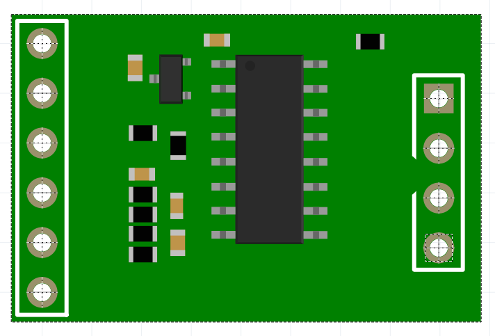
Fritzing:
The likely answer is that you have a translate in the svg and Fritzing is misinterpreting it. I’d suggest uploading the svg (if it won’t upload as an svg which sometimes happens, rename it from .svg to .fzpz and upload that, telling us that it is really an svg). In Inkscape ungrouping then regrouping will most of the time remove the translates.
Peter
I saw the translates (which were caused be my resizing a very similar part to create this one) and removed them. I will upload the files.
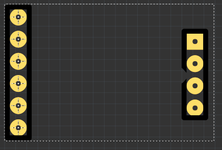
SVG, image is hard to see -->![]()
Ah, I was incorrect. Your problem is likely you are using paths for the pads. Fritzing uses the circle diameter and stroke-width in a python script to generate the gerber output, while I’ve seen a number of people (even in core parts!) use paths for pads, I’ve never seen a case that worked correctly. Here is the connector xml from a generic 16 pin connector from core (what I had easily to hand  ):
):
        <circle cy="70" gorn="0.2.0.0" stroke="rgb(255, 191, 0)"  fill="none" r="29" stroke-width="20" cx="70" id="connector0pin"/>
        <circle cy="170" gorn="0.2.0.1" stroke="rgb(255, 191, 0)"  fill="none" r="29" stroke-width="20" cx="70" id="connector1pin"/>
if you substitute this in to your svg it should work better. This sets the hole size to .038. If you need something different (and are using Inkscape ) it is set by circle diameter (in inches) - stroke-width * 2. In this instance the diameter is .078 - 40 = 38 thou (note sometimes Inkscape uses odd units in stroke width and this then doesn’t work right) which gives 38 thou as the stroke width is 20 (and units this time in xml editor are in thou). You are usually best to start from either a generic IC from core or a generic connector from core both of which have appropriate settings in the svg. The trick to the svg image (as I have just discovered lately) is to right click on it and then save as image to recreate the svg. Sometimes the forum won’t render the svg and then I don’t thing that works, but in this case it did.
Peter
I will try that, but it doesn’t explain why the breadboard image, which I copy pasted these elements from, works as expected.
I guess I will just start over completely. So much for saving time by modifying an existing part. 
Thanks for your help.
That works to a point (I do it lots), but unfortunatly parts quality varies so you need to be aware of what the xml should look like (which comes with experience in parts making) to be able to evaluate whether the part you are copying is going to work. I often mix and match bits and pieces from various other parts to get where I want to go (and steal good artwork in breadboard since I’m no kind of artist). If breadboard is working I’d keep it and just change pcb if that’s all that’s breaking. If you upload the final result I or one of the others of us will have a look and point out errors. Its in all our best interest to encourage people to make more parts ![]() At some point (which unfortunatly isn’t yet) we need to do an audit and correct on the core parts distribution to correct the existing errors (the grove parts for instance all seem to use the path for pads which doesn’t work). I’m slowly working on a python script to check and correct for Fritzing which objects to some of the things such as CSS style xml that Inkscape does, but again I’m not entirely there yet. That script will complain about connectors that aren’t in one of the known working geometries (I having been bitten by paths before
At some point (which unfortunatly isn’t yet) we need to do an audit and correct on the core parts distribution to correct the existing errors (the grove parts for instance all seem to use the path for pads which doesn’t work). I’m slowly working on a python script to check and correct for Fritzing which objects to some of the things such as CSS style xml that Inkscape does, but again I’m not entirely there yet. That script will complain about connectors that aren’t in one of the known working geometries (I having been bitten by paths before ![]() ).
).
Peter
Are the pads that work “circle”, and the pads that don’t work “path”
If you can’t figure it out upload it with the 7th button and someone will have a look.
He did upload the svg. If you right click on the end of the arrow above and save image to file you will get his svg. The forum is rendering it there, just very small (if you peer closely you can see the tiny pcb pads). That’s how I know the pads are a path.
Peter
Turns out I was maligning core parts unjustly  , in fact I had loaded this part (from elsewhere on the net) and mistakenly though it was in core.
Grove Ultrasonic Ranger.fzpz (9.9 KB)
At least one (and I suspect all) of the grove parts in core have been corrected. If you load this part in to fritzing it will look just fine in all views. However when you export the gerbers you will find that the drill file contains no holes (because the path does’t create them):
; NON-PLATED HOLES START AT T1
; THROUGH (PLATED) HOLES START AT T100
M48
INCH
%
T00
M30
As well the pad images in the gerber are pixalated somewhat. So long as you stay in Fritzing, things will look fine (which is why breadboard appears OK), but when you want to produce boards, trouble comes because of the path command in the pcb svg.If you load the above part in to Fritzing you will see what I mean, within Fritzing all looks fine but export gerber doesn;t actually work.
Peter
Is there a “library” SVG somewhere that has a collection of typical pads, etc. so that I can just copy paste what I need instead of reinventing all this stuff that has probably already been created hundreds of times?
After drawing the PCB again with “circles” everything works. Thanks for the help.
I usually use the generic IC from core and set its number of pins to match the number of connections I need. That creates the appropriate pins,their connections and the pads in all three views and can then cut and paste around them to get the part running. The one annoying thing about it is the connection terminal pads are set to 0 height and width. That means that Inkscape won’t select or move them, so the first thing I do is change the width and height to 10 for all the terminal rectangles so they will be selected and moved when moving a connection.
Peter