The Sparkfun push button is missing the internal connector wire for the shared pins. You will become aware of the problem if you use both pins of either set with the assumption that they are connected. Neither the schematic or PCB view will understand that this connection exists.
What I expected should have happened instead:
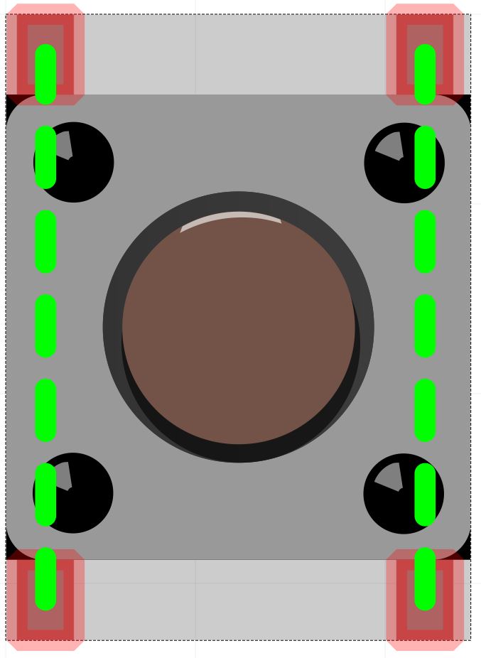
These buttons have pins (1 and 2) and (3 and 4) internally connected. While the schematic view visually shows the correct connections, the internal connections are not included.
My version of Fritzing and my operating system:
Fritzing version 0.9.3b on Windows 10
Please also attach any files that help explaining this problem
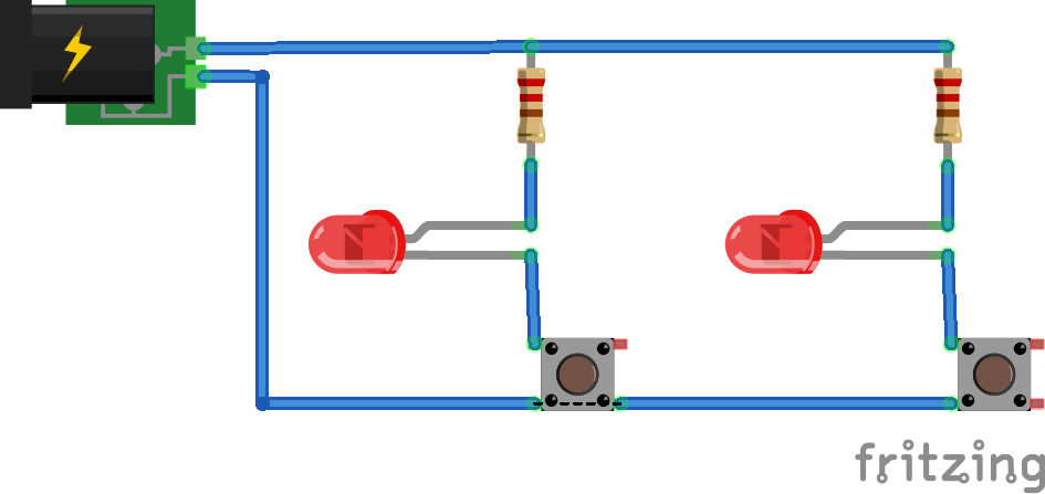
This is an example of how these pins should be used:
If you would like to fix it yourself you can open the part in the parts editor (right click on the part and click edit). Then in Breadboard or PCB view you will find a small check box on the right just below the connectors list that says “set internal connections”. Check that box and then draw the connections on the part that you want. Then in the Metadata tab change the variant name and possibly the title and description. Now you just need to save it as a new part and restart Fritzing. Once you restart Fritzing you will be able to click on the existing part in your sketch and then go into the inspector and change the variant to the new one. You can also just find the part in you “mine” pats bin and use it directly.
I took another closer look at this and found that the pins are not connected internally.
The four pins light up individually in all views. I will admit that the problem was not easily visible until I started to set up my ground indicators and ground fills.
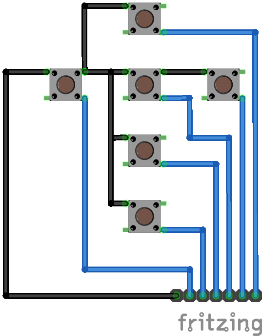
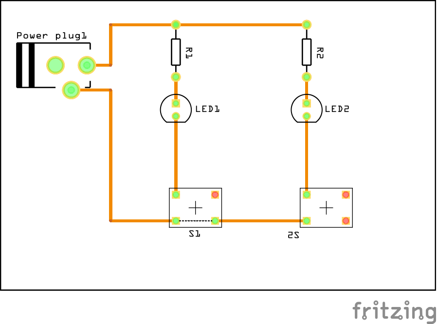
To illustrate the problem (or demonstrate that I’m using fritzing wrong), I setup a very simple circuit. Note that I didn’t bother to set the resistor values.
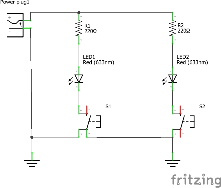
Note that the addition of the ground references in the schematic diagram is what causes the rats nest lines to be added across the switch.
I assume that this occurs because the ground references are telling fritzing that both points should be connected to ground. I originally had one reference to ground and when I created the ground fill to my surprise the wires after the switch were not ground referenced.
I tested this by creating a derived switch that just adds the two connecting wires and the problem is solved.
I suspect you are using the through hole version of SKU COM-00097, so I added the bus definition as @sublimeartistry suggested (but by editing the fzp file rather than using parts editor, which would do the same thing) to make this functioning part There are also other (non sparkfun) switches that act correctly (I expect one of those is what @Old_Grey is using that functions correctly). You can load the original part by searching for com-00097 in the parts search bar (which I see matches three different parts all apparently wrong), or just replace (delete minus will allow you to replace the part without redoing the routing) with this corrected one.
Yes at some point we need to clean up core parts to correct the various incorrect parts, but so far that hasn’t happened. If you would like to help with that you can do so by fixing the broken parts in a clone of the parts repository from github and then make a pull request to replace the broken parts.
I took a look at all of the “pushbutton” parts. It appears that all or most of the Sparkfun pushbuttons have problems. Some of them don’t connect the pins internally as I discovered and others show all four pins but only let you connect to two of them.
I did, however, note that the “Tactille Button” objects all work correctly. That’s the one with the big colored tops.
I’ll try to make some time to make some corrections and submit them. The submission process is new for me as is using fritzing, so it might take some time.
Welcome to the world of free submitted parts made with no compulsory standards, checking. or approvals.
If someone only needed a footprint to make a PCB they would just make that, and fill in the other views with svg’s from other parts as approximations because they won’t be using those views. Even then non-engineers make parts and don’t realise that footprints have to be accurate engineering drawings or parts won’t fit - usually they are close enough if not totally accurate -.
It is to me as well, and I’m poking at development (because somebody has to do it). I have a parts checking script that will tell you some structural things are wrong (but not something like the lacking connections, that need a human). There is also a method of obsoleting bad parts, but it as far as I know is TBD as far as documentation goes. If I get some time I’ll poke at that as well. If we can get some people interested in helping Fritzing can get better, if we can’t it is going to stagnate (and I don’t want to see that).