That actually looks fantastic! At least for me, as I’m a beginner in this field and I hope I’ll do something like this myself one day 
TB6560-Stepper-motor-driver-Arduino_b84191f4ce6d1ca5a1e05f569c021254_5.fzp (7.8 KB)
Hi everybody. Some days ago I bought a TB6560-stepper-driver for Arduino. Then I decided to create the breadboard in Fritzing for my projects. Now I have the opportunity to share with you.
1 Like
Hi once again! I haven’t created anything myself yet, but recently I came across this site and they have published there 3d models they do with their scanners. I mean, it’s just a lot of inspiration, isn’t it?
MCP9700-ETO_Temperature_Sensor.fzpz (6.7 KB)
HIH4000-00X_Humidity_Sensor.fzpz (7.7 KB)
Hi all these are my first 2 parts, a temperature sensor (MCP9700-E/TO) and a Humidity sensor (HIH4000-001).
I created all 3 view for the sensors. Please can someone check if I did the right work? thank you for help
seeed_grove_Touch_Sensor.fzpz (9.5 KB)
seeed_grove_Rotary_Angle_Sensor.fzpz (10.3 KB)
Hi all these are my 2 parts, 2 sensor of Seeed Grove (rotary, touch sensors ).
I created all 3 view for all the sensors. Please can someone check if I did the right work? thank you for help
seeed_grove_Sound_Sensor.fzpz (10.4 KB)
seeed_grove_Magnetic_Switch.fzpz (10.8 KB)
Hi all these are my 2 parts, 2 sensor of Seeed Grove ( magnetic, noise sensors ).
I created all 3 view for all the sensors. Please can someone check if I did the right work? thank you for help
Not too bad, but you have a few problems: In breadboard the pins are not on .1 centers (that is OK if in real life they also aren’t on .1 centers, but that seems less than likely). Schematic you should eliminate the nc (which I’m assuming is no connection) from the pins and probably label the signal connection as signal. You also need to set a connectorxterminal in the schematic svg to place the connection point on the end of the pin. The definition is in the fpz file, but isn’t present in the schematic.svg and thus the wires connect to the middle of the pin (which isn’t correct). I usually use a .01 by .01 rectangle with fill=none as a terminal.
Peter
why i cant use it? is it bcs .fzp?
Yes, the file is only the fzp file, to work it also needs the four svg files zipped as an fzpz file. The original poster would need to post the entire part …
Peter
@Steelgoose By chance, do you have a couple of 10 pin picoblade connectors in your bucket?
I’m not sure it is a picoblade connector, but is is 10 pin connector at a right angle. The is attached to a ribbon.
While I’m not SteelGoose there are picoblade connectors in core (not 10 pin that I can see though) so making one shouldn’t be a big deal. What is the pin spacing and what does it connect to (if its for an lcd it may be a ffc connector). I’m assuming smd because most of the fine pitch ones are.
Peter
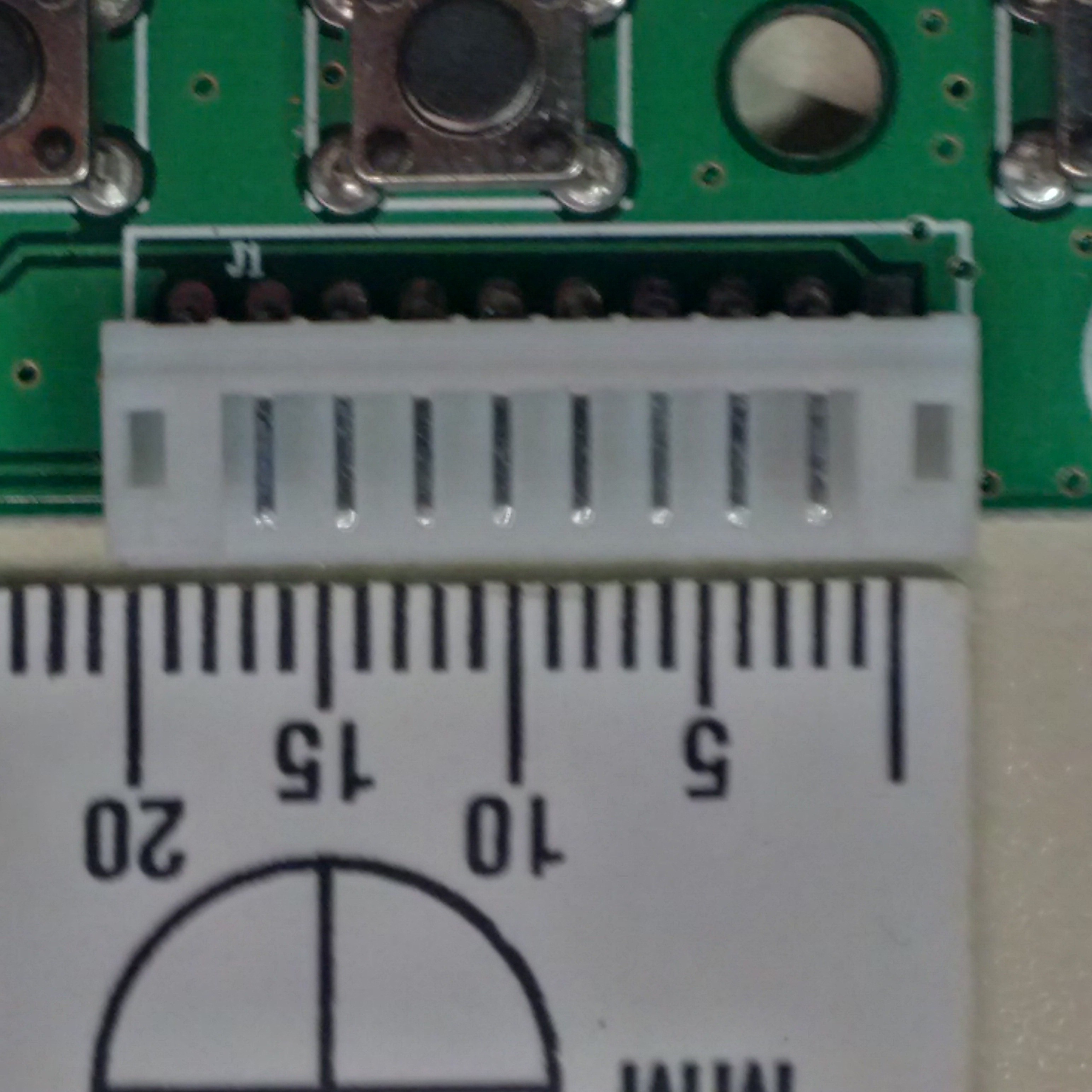
Thanks Peter, It is for a 5 button board for an LCD. It connects to a HDMI driver board via a ribbon cable. I can attach a photo if you’d like?
Have you got a part number for the board? That would probably tell us what the connector is as there are several types of ribbon cable around from standard .1in spacing, 2mm, I think 1.27in and ffc at .5mm and probably others I don’t know. We would need to know which one it is to get it accurate on pcb.
Peter
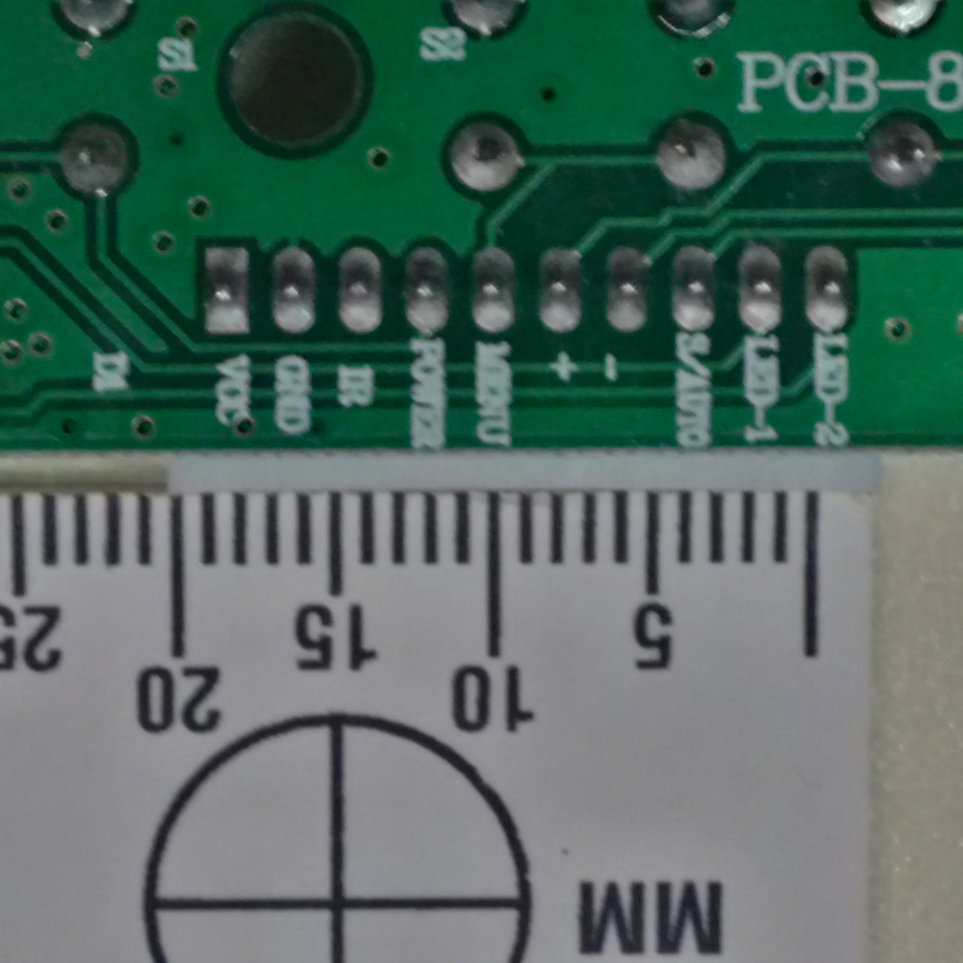
The board number is PCB800023. The pdf I have shows two of the connectors, but this board only has one.
The keyboard attached to one of these?
If so I suspect you are correct it may be a picoblade connector with cables rather than ribbon cable and looks to be on .1 centers. They specify the lcd ribbon cable connector but not (that I can see) the keyboard one. If you measure the connector across the 10 pins is in 1 inch (which would indicate .1 spacing)?
Peter
yes, the one on page 13, #2109. 5" Touch. Has the grey looking ribbon cable.
I will have a better look at it tomorrow, with some magnification.
If you have a .1 header you could compare it to the connector and see if they match up.
What I’m looking for is the spacing between pins (although really I’d like to know what the actual connector is so we get the correct footprint).
edit: Actually assuming you want to make more of these, you will in fact have to figure out what the connector part number is so you know what connector to order to mate with the ones on the board. So look for a part number or a manufacturer’s logo on the connector is probably your best bet. I can’t see anything that says what the connector part number is anywhere.
Peter
No numbers or markings of any kind on the parts. I’ve tried to attach a couple of images of the parts. Sorry for metric markings

If you follow the links the UBER guide to the driver boards datasheet you will find that the driver and button board are made by this company http://www.tftlcdcn.com/ which you could email and ask for the plug information.
This good suggestion is probably your best bet. Connectors are ugly because there are so many of them (these look to be 2mm pitch and thus likely not picoblade which looks to be 1.25mm pitch). Unless you are replacing both ends (in which case you can use whatever you want ![]() ), you need to find the exact connector so that the cable will plug in correctly mechanically and if you don’t have a part number that is hard as there are so many variations.
), you need to find the exact connector so that the cable will plug in correctly mechanically and if you don’t have a part number that is hard as there are so many variations.
Peter