This is a Fritzing schematic template file for use when you want to make a schematic svg from scratch (which I usually do as I find it easiest). It is set to the proper scale as explained in this howto
and the fonts, font sizes and colors match those called for in the graphics standards here:
http://fritzing.org/fritzings-graphic-standards/
This simple one has connectors with terminalIds and labels on all 4 sides of the rectangle with the text-anchor set to the value appropate for the position. The label has text id label which is special, no matter what you put in it in the svg, it will be replaced with the text from the title field of the fzp file by Fritzing when the svg is loaded. If you (as I often do) want to put text that will not be substituted, change the id label to text1234 (really anything except label) and the substitution will not be done.
svg.schematic.simple-schematic-template_1_schematic.svg.fzp (6.4 KB)
This is the svg file itself so you can load it and play with it. Note you need to remove the trailing .fzp because the forum has trouble with svg files but will accept an svg file called a fzp file just fine (and it turns back in to an svg file when you remove the trailing .fzp.)
The advanced template below, adds the “group connectors” part of the graphics standard and details how I deal with dual row headers in schematic. This maps the linear nature of schematic to the physical (dual row) real world connector to make it obvious which pin is which on the physical connector. It also demonstrates how to do “group connectors” that meet the requirements of the parts file format document.
svg.schematic.group-connectors-schematic-template_1_schematic.svg.fzp (9.5 KB)
With that established a brief example of making a schematic from the simple template. The part I am going to make is a motor driver labeled Fake Part with direction and speed inputs and two output terminals for each motor. To start first load the simple template file in to Inkscape. Note due to the forum often having trouble rendering svg files, you need to down load the above .fzp file, then remove the trailing .fzg to get the svg file to load in Inkscape.) Next File->save As, change the file name from svg.schematic.simple-schematic template_1_schematic.svg to svg.schematic.test_1_schematic.svg so you don’t overwrite the template file on a save (if you do, you can just reload it though!) Now View->Page_grid to show the page grid (which hopefully is set by your preferences file to this) :
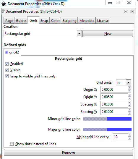
if not set your preferences file via:
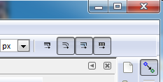
Now insure that ‘Edit->preferences->Behavior->Transforms->Scale stroke width’ is unticked, the easy way to do that is via the tool bar by clicking this icon till it is light (unticked). If you do not do this Inkscape will increase or decrease the stroke-width of an element when you increase or decrease its length or width. We do not want the stroke width to change, we want all (or at least most) lines to have a stroke-width of 10 to match the size of a wire in Fritzing at this scale.
then set the tool bar units to in (for inches). That (after zooming out a bit and selecting connector0terminal in the xml editor) should get you this:
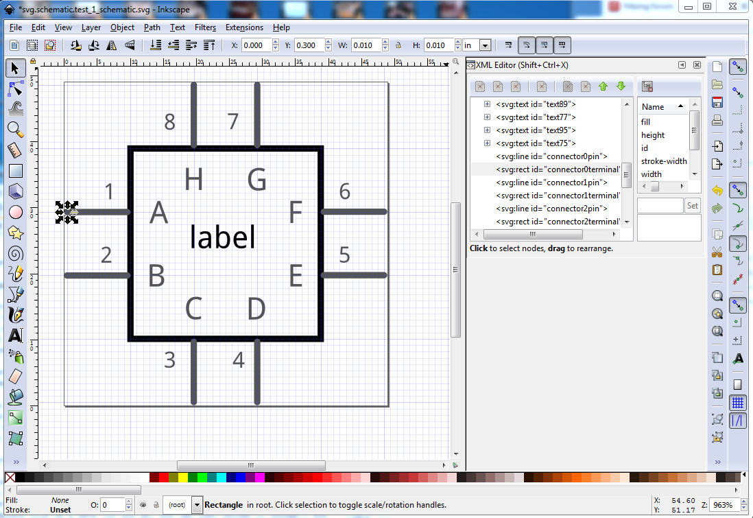
Of note in this image is that the grid is set at .01in for minor lines and .1in for major lines (the darker blue). The border rectangle. pins and terminals (with some exceptions for the pins which are offset .05in on the top and right side of the rectangle) are on .1 in boundaries as sbown by the x/y coords at the top of the tool bar. This layout produces this:
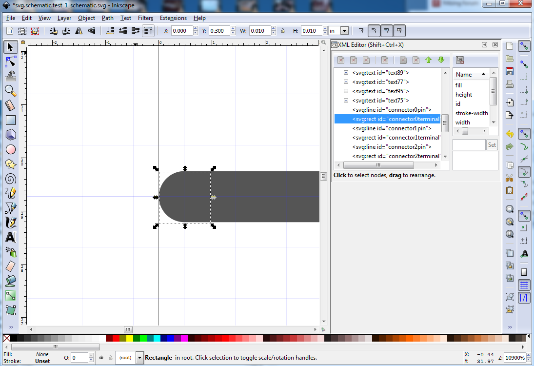
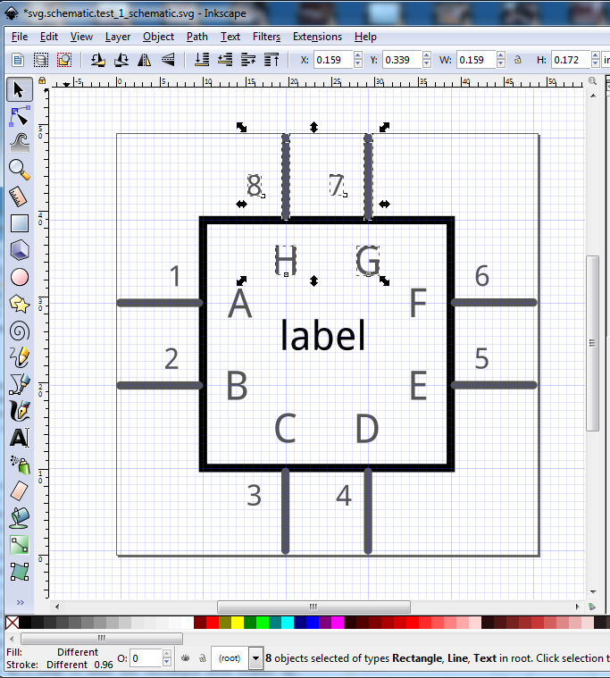
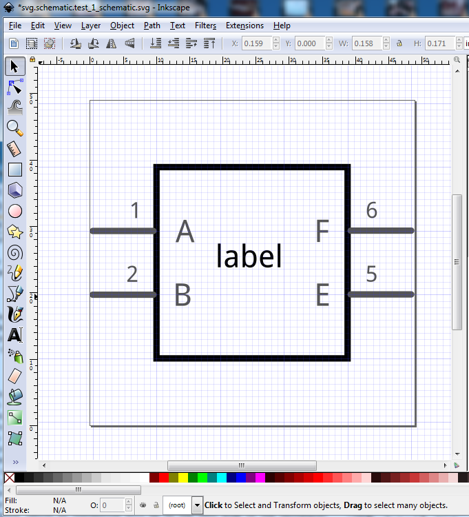
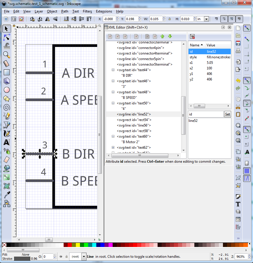
Here we see that the 10 thou square that is connector0terminal exactly overlaps the rounded edge of the 10 thou stroke-width connector0pin. The result of this is that a wire connected to pin 1 of the part (connector0terminal) will mesh exactly at any angle with the pin of the part. A very common error is to forget to add connector0terminal in schematic, and thus the wire will connect in the center (i.e. 0.05 in to the right of the position of connector0terminal) making an ugly and incorrect connection for anything except a straight in connection. In addition with Inkscape set like this, if I put a selection box around connector0pin and connector0terminal, duplicate them and then click the up or down arrow on the x or y coord on the tool bar, the new pin will move exactly .1 in in x or y (depending on which button you click) creating a new connector (but without the correct ids) and positioning it correctly. It is possible and efficient to do entire groups (2, 4 however many you need) connectors the same way. For now I am going to assume this schematic needs to 2 pin inputs (which by convention will be on the left side of the rectangle) and two 2 pin output connections (by convention on the right side of the rectangle) and that I need some longer pin labels so I need to make the rectangle both higher and wider than it currently is. But first I need to delete the unwanted pins on the top and bottom of the rectangle. To do so draw a selection box around them and hit the delete key.
Note that I selected all of the connector line, the connector terminal and all the labels, I then did the same to the two terminals on the bottom of the rectangle and deleted them as well which results in this:
Now I am ready to duplicate pins 1 and 2 to make and place a second 2 pin connector on the left of the rectangle. So drag a select box around the pin terminal and labels for the two pins like this:
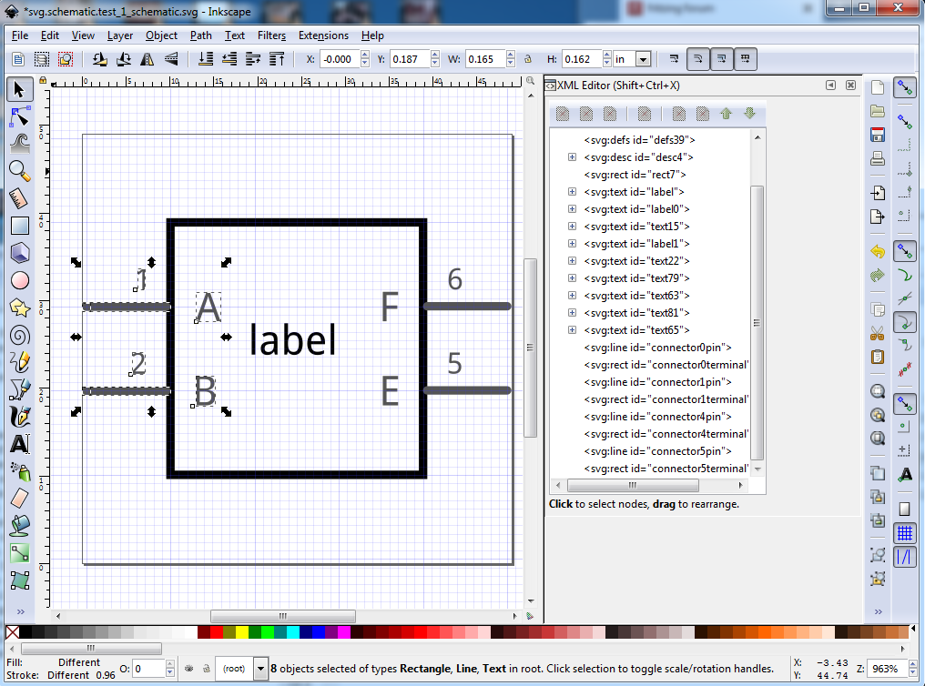
then right click and select duplicate to do the duplication. Nothing in the canvess appears to change because currently the duplicate are on top of the original elements. However in the xml editor window on the right we see a bunch of new elements (the same as those we selected but with new ids) have appeared as a result of the duplication. The elements outlined in blue (the text elements are probably not correct, but the number of elements is) have been duplicated and re id ed in to the section in red creating our two new pins on top of the existing ones and (conveniently) selecting them.

Now if I click on the X coord down arrow bar here three times:
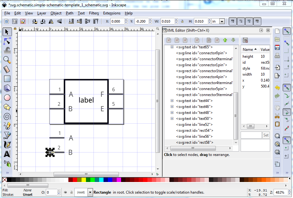
the selected two connectors move down in y by 0.3in leaving a 0.1in separation between the two connectors leaving the original connectors in their original position. In general it is desirable to make schematic as small as possible so as many parts as possible will fit in a single drawing. As well you will note that this movement has moved the new 1 B connector outside the viewbox, which would cause it to be truncated by Fritzing if loaded like this. We will fix the view box later though. Now I am going to do the same thing (without the images) to the F and E connectors on the other side of the rectangle. Now I will select the rectangle and move it down 0.3in in y the same way, leaving its new staring point at -0.200in. Now switch to the H increment bar and click it 3 times to increase the height of the rectangle to 0.61in restoring the rectangle to being 0.1in below the bottom connector and 0.1in above the top connector as is desirable. I have arbitrarily decided I am making a two channel motor driver module, with inputs for speed and direction and outputs for the motor terminals. As we see there is not enough room for the necessary pin labels (and label is in the wrong place but we will fix that later). Becasue the viewbox line through the middle of the part is annoying me, at this point I’m going to do an Edit->select all, then click Document Properties->Resize Page to content…->Resize page to drawing or selection to reset the viewbox to surround the part (I will do this multiple times as the document changes to keep it readable). That produces this:
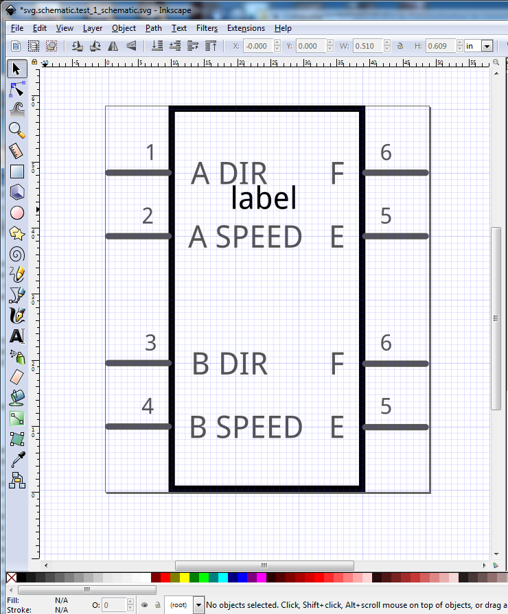
Now I need to move the connectors on the right side of the rectange further to the right to make room to add the text for the two motor connections on the right and then resize the width of the rectangle to match the new connector positions.
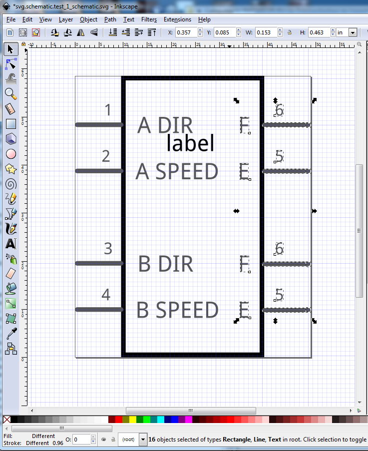
Note I started above the select box rectangle back at the trailing characters of the label and left side connector labels. Because the entire element of the label text and the rectangle are not in the select box it only selects the connectors that I want to move. That produces this:
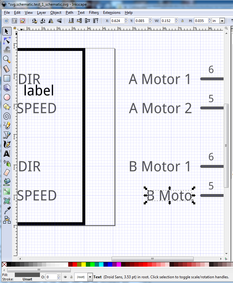
I intentionally captured this while only part way through entering the B Motor 2 text to illustrate the use of text-anchor start, end and middle. In this case the text-anchor is set to end:
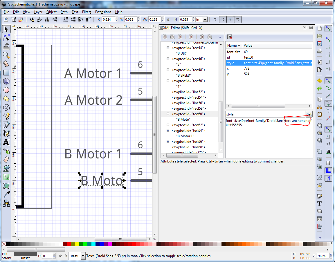
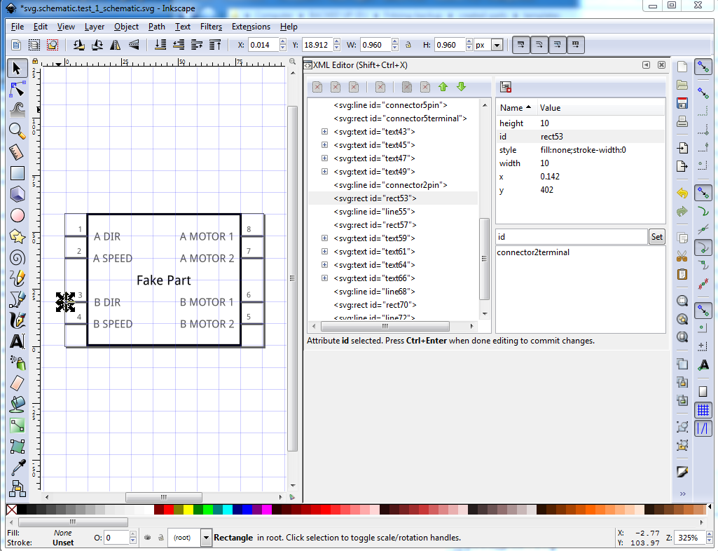
That means the text is anchored to the end of the characters and as I type in new values in the xml editor it will expand the text to the left, leaving the last character in the correct position from the pin and the rectangle (when I move it there.) The label is set to text-anchor:middle and thus will expand to both left and right leaving the center of the text in the approptiate position, and the labels on the left are set to text-anchor:start so they will expand the charaters to the right leaving the start character the correct distance from the pin (as long as its initial position is correct which it is in this case.) All of this is in aid of lazyness, doing this I don’t have to (at least usually) reposition the text after making a change. lazy is good as far as I am concerned. So I finished the text, and changed label from label to Fake Part, but in this case that doesn’t matter. Because the text id on the Fake Part text is set to ‘label’, Fritzing will substitute the text from the Title field in the fzp file in place of this text and the final part will have whatever test is in Title in place of Fake Part. If you want Fake Part to appear no matter, change the id field from label to label1 (really anything other than label) and the substitution will not take place. Now the part is cosmetically complete. The only thing left to do is to correct the pin definitions (remember the connector0pin and connector1terminal fields were changed to line123 and rect123 when we duplicated them) so we need to use xml editor to assign the pin numbers that are specified in the fzp file to the appropriate pins (this can also be done in Parts Editor although I am rarely successful doing it and thus avoid Parts Editor.) In this case I will assign the connector numbers as one less than the pin number i.e. Pin 1 in the drawing is connector0pin, pin 2 is connector1pin. Confusing, but how Fritzing wants the pins labeled. Pins 1 and 2 (connector0 and 1) are correct from the initial part so we start with pin 3 (connector2) and use xml editor to set the id field on the line to connector2pin and the rectangle below it to connector2terminal which looks like this currently:
and wants to change to this with connector2terminal ready to be set:
repeat for all the rest of the pins to give:
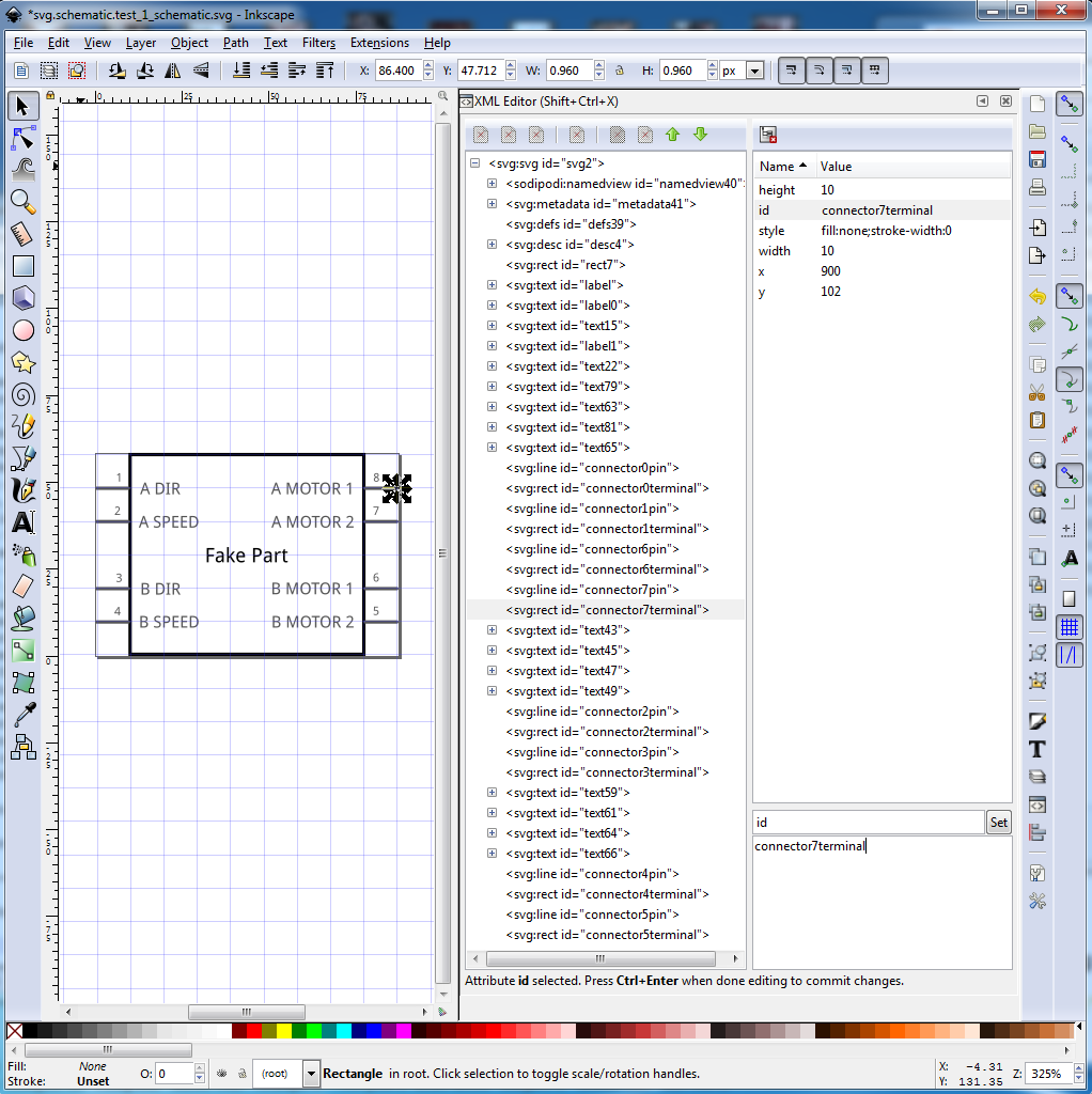
At this point, schematic could be considered finished as it will work without problem as is. I prefer to do one last optional step to make later maintenance easier: Arrange the pins in order at the bottom of the xml edit window so they are easy to find by doing this:

With the pin (and then the terminal for that pin) selected press the tool bar button outlines in red. That moves the pin to the bottom of the xml window. Repeat with the other pins to end up with this:
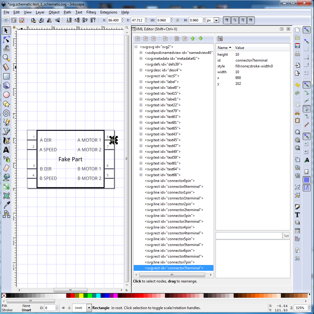
Now we are ready to resize, regroup and save the finished svg. So Edit->Select All, then click Document Properties->Resize Page to content…->Resize page to drawing or selection to reset the viewbox to surround the part. With the edit select all still active use either cntrl-g from the keyboard or Object->Group from the tool bar to create a group from the entire image like this:

then File->Save as and change the file type to Plain Svg as shown in the red highlight here:
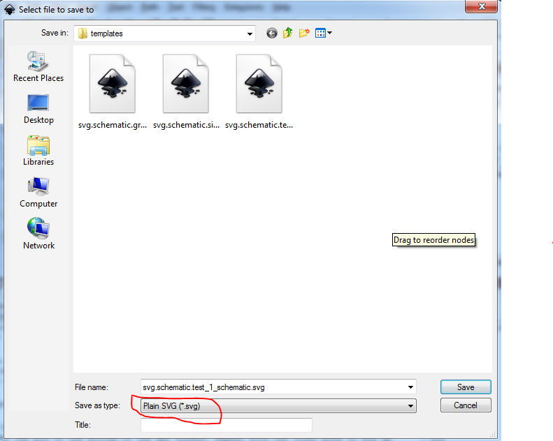
to save the svg file in a Fritzing friendly format. Now you have the schematic and can proceed on to make the rest of your part.
 . The template files for instance are currently totally wrong and many core parts (and worse the parts factory code) don’t meet the standards. A work is slow progress …