Yes, good find! This is exactly what you want. Didn’t show up on any of the google searchs I did. I’ll have to remember this in case I need one sometime.
Peter
Yes, good find! This is exactly what you want. Didn’t show up on any of the google searchs I did. I’ll have to remember this in case I need one sometime.
Peter
Hi J303
If you fancy building your own split supply you can take a look at this (I’ve designed this layout and built it. I use it for my modular synth):
:12V Rack Power_1.02.fzz (55.9 KB)
It is based on the MFOS project here:
http://musicfromouterspace.com/analogsynth_new/WALLWARTSUPPLY/WALLWARTSUPPLY.php
There’s also some nice schematics on Hexinverters site of all the 909 drums and a few 808 voices too.
http://www.hexinverter.net/neinohnein-kick/
You might also find these parts useful:
RE: spilt power: You can make a battery powered split supply. Here’s a guide on how to do it:
Good luck,
Kevin.
Is there no way to make this work from 9V batteries? How does Eric Archer make the Andromeda Space Rocker? It seems this whole circuit should be able to run off of two 9V batteries.
http://www.ericarcher.net/wp-content/uploads/2014/07/mk4-v2-kit-instructions-0.pdf
Same with this other clone, that is modeled on Eric Archer’s schematic
It runs on +/- power supply, you can run 2 9v batteries in series, or run it off a bipolar (+/-15v or +/-12v power supply). Or… experiment!
As long as it will run on +/-9V (which the second article seems to indicate it will) then 2 9V batteries connected as in noodleDriver’s Split Supply Concept drawing should work just fine. Won’t hurt anything to try it, low voltage won’'t damage anything in the circuit, at most it won’t work if the transistor bias is off far enough (but that’s somewhat unlikely).
Peter
2 Batteries will work just fine and will not hurt anything in your circuit but as they loose charge the voltage will drop and maybe make it sound a bit different ie drop in volume or some minor thing. At some point the voltage of your batteries will droip below (3 or 4 volts) the minimum voltage for some component. I think op amps like TL072 work right down to 3 or 4V then they just stop working (ie you will hear no sounds) at which point you just replace the batteries! This method will work for any circuit that requires a split supply. Of course you could use 2 x 12V batteries but they are not so common unless you use 2 car batteries or something crazy! I have used both methods to test modules (2 x 12V car batteries and also 2 x 9V square batteries. However, it is quite easy to find an old 24VDC wall wart in your attic and use a resistor divider to make a virtual ground then 2 big caps for smoothing.
This page shows the various methods described above:
https://tangentsoft.net/elec/vgrounds.html
Kevin.
Thanks for that link, I really had no idea dual power was a requirement for anything, ever. This all must be done internally in the TR-808 or TR-909s.
I am glad you sent me that page, because I was quite confused by the schematic from Eric Archer, his schematic has some generic capacitors across to ground. I then looked at a PCB built by jmej and the board has two electrolytic caps to ground on the dual voltage.
I see the same pattern from the link you pointed to -> using electrolytic caps
Jmej
https://www.muffwiggler.com/forum/userpix/1043_808bs_sc_2.jpg
In modular synths the power supply will be fixed to the case and shared between all the modules via a distribution bus. There’s no point making a seperate power supply for each module.
The 808 is MAINS powered and has an internal (center-tapped) transformer which converts this down to some useful voltages.
I strongly advise against using a VCT transformer as this is potentially LETHAL! (You could die if you make an error!!!)
Stick with the Adafruit split supply as this takes care of all the deadly bits for you…
When you build enough modules to exceed the 500mA per rail provided by the Adafruit PSU you can either buy another Adafruit supply and keep doing that or buy a nice modular synth case/psu like the Doepfer LC9 or a microZeus by tiptop audio http://www.tiptopaudio.com/zeusmicro.php.
There are a lot of cases to choose from that are factory made but obviously they cost a lot more than building your own.
I built mine for under £20 and it can provide 750mA on each rail (+12V rail and -12V rail)
Hey thank you Noodle, Peter, Oldgrey.
I tinkered a while with this circuit using the 9V batteries in series and an Arduino to provide a trigger from pin 13 so I can see the LED flash when it triggers. It currently produces a loud “click”. Definitely sounds like the initial fast attack pop at the start of the 808 bass kick. From what I read, using 9V batteries will only produce this kind of click. So I am waiting for the Adafruit power supply although the DC/DC power supply from Murata looks very good.
I noticed the batteries got very hot rather quickly and lost charge fast.
From what Eric Archer mentioned, the Accent needs to be tied to (+), I am sending a short 5V pulse from the Arduino.
Here are some references for what is necessary for this circuit to work:
Electro-music.com forum thread about this circuit
Original Web Site (archive of Ericarcher.net)
Here is what Eric Archer wrote about the device:
Trigger and Accent inputs - Each drum has a TRIGGER and ACCENT input. In the 808, the accent input is a global signal that boosts the level of all drums when requested (TTBOMK). In my clone, I just have a potentiometer set up as a voltage divider to deliver a constant voltage to the ACC input. It is basically a volume control in this arrangement. The trigger inputs are a little more tricky; if you are driving the drums with a logic circuit, you’ll need a little bit of trigger generator glue inbetween. Basically this lets the energy of the positive transition thru to trigger the drums, and shaves off the negative edge. If you omit the trigger generator, the drums sound weird b/c they will also trigger on the negative edge, with a different and weaker tone, reduced decay time weird.
Youll need a split power supply to make these circuits work. You can use +/-12VDC or +/-15VDC. In a pinch you can make a +/-9VDC supply with two 9V batteries and a pair of battery snaps. Or you can adapt an old PC power supply to make a +/-12VDC bench power supply. Look for instructions on how to hack a PC supply on the net.
Or do what I did: I found that the miniature muRata NDTD0515C DC-DC converter works nicely, boosting juice from a cheap wallwart up to nice +/- 15VDC bipolar power.
From a forum entry:
i’ve just finished building this circuit and have some results to share, for what they’re worth.
i’ve run the circuit at 9V, 12V, and 15V and can say that the sine/click balance is directly proportional to the source voltage.
at 9V the sound is exactly like the samples posted above where the click was by far the most predominant element.
at 12V the sound is very, very close to authentic.
at 15V the sound is as close to owning an 808 as i’ll ever get!
I will post results once I have the circuit connected to the 12V+/- power supply and I’ll post the breadboard.
I don’t think that should be happening. If you have a multimeter or amp meter measure the current the circuit is taking. Hot and fast charge loss likely indicates you have a short across the power supply somewhere. Op amps don’t usually draw all that much current unless you they are driving a low impedance load and I don’t think this one is so you are likely looking at a wiring error of some kind.
If it likes 15V best, then the Murata (although a bit pricey) is a good bet. A cheaper alternative would be 2 15V regulated wall warts (with the disadvantage of needing 2 power plugs)
Peter
I got the Adafruit power supply, in the description for the product
The black wire is your every day classic +12VDC with center positive. The white wire is the negative supply, its also center positive which means the center is the same as the black wire’s ground. The ‘ring’ of the white-cable connector is -12VDC. You can draw about 500mA from each side, a total of 1A
How should I hook it up then?
Center of black wire is + 12V
Tie the ring of black wire and ring of white wire - GRND
Center of the white wire -12V
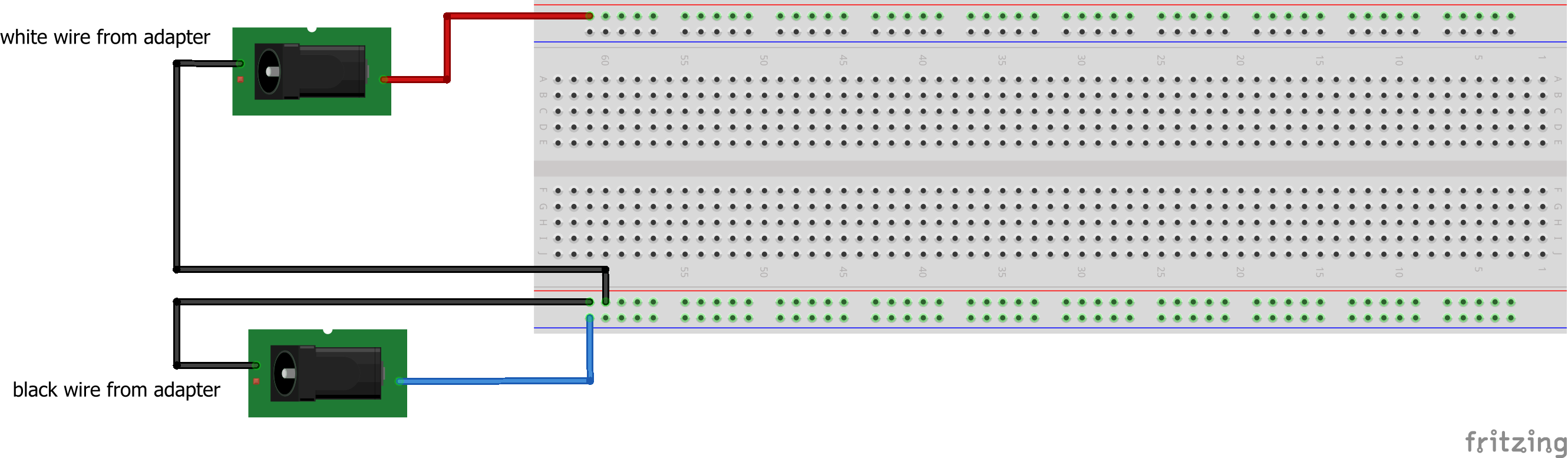
So if I follow your schematic, the +12V and GRND goes to the very top +,- rails and the -12V goes to that rail in the middle (as in your breadboard)?
From reading the data sheet from adafruit this should do the job:
the white wire from the wall wart has +12V on the center pin and ground on the barrel, so the center pin goes to +12 with the red wire and ground goes to ground. The black wire is the same except the center pin there is -12V and thus goes to the -12V rail and the outer ring is ground and connects to the ground rail. In the drawing the red and blue wires connect to the center pin of their respective connector and the grounds are the outside of the barrel.
Peter
I just came across this on ebay which would replace the Murata at less cost (but long delivery).
Peter
Thank you for that.
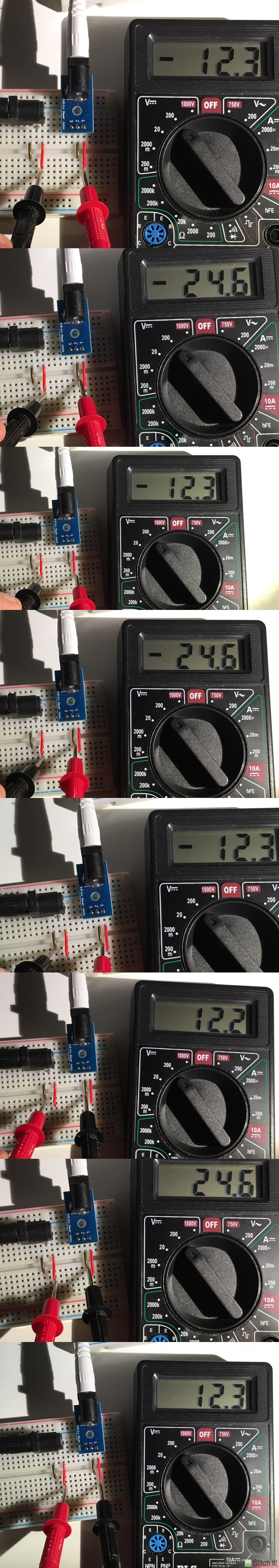
I tried connecting the jacks like you have drawn but it seems odd, I was testing to get the 24V across the leads but I don’t see that. I think the powersupplies are already connected internally so that connection of the black cables isn’t needed… I am confused… and I somehow popped a capacitor while tinkering, I don’t want to die…
I’ve taken pictures of the -24V, the +24 and it looks like the ground is internal to the power supply.
Something about that doesn’t look right. If you measure between the black and red leads on the connector to the white cable from the adapter do you see +12V? If not, I’d check the wiring on the adapter board as pin 1 should be connecting to the pin on the end of the connector (which in turn should be the center pin of the plug from the adapter) and pin 2 should be going to the barrel of the plug. From what the voltmeter is reading I suspect you will find the black and red wires on the right hand (white wire) barrel connector are backwards, i.e. red is ground (and thus the -12v to the red wire on the other connector which looks to be connected correctly). If that is true then if you move the red meter probe to the black wire on the same connector you should see the expected 24 volts.
Peter
Yes, I see +12V when I measure : red probe -> red lead, black probe -> brown lead for both the white and black jack. I expect this.
Ah, I think I see the problem. The brown wires appear to be ground, so with the black meter lead on either brown wire the red wire on the white cable should read +12V which it seems to, and with the red probe connected to the red wire (which I would suggest moving to a blue or some other color wire to indicate -12V to avoid confusion) and the black probe still on the brown wire you should measure -12v/ If you put the black probe on the red wire on the black adapter cable (-12v) and the red probe on the red wire of the white cable you should get the expected +24V (and reversing the probes would then show -24 V as seen by the meter). I think you are hooked up correctly and just having problems with measurement. The meter sees the black probe as ground and measures positive or negative voltage relative to the red probe. Voltage is additive so if you put the black probe on -12V then the brown wire (ground) will measure as +12V (because it is 12V higher than -12V) and +12V will measure as 24V. You are likely correct that the two grounds on the white and black adapter cable are connected together internally in the adapter.
Peter
So given that the ground is internal, where do I connect ground?
To either of the brown wires. Ground being connected internally isn’t an issue, however you only want one path to ground, so either one (but not both) of the brown wires can become ground. If you connect both brown wires to ground you have what is called a ground loop (essentially two parallel paths to ground) which can cause problems. The same is true when connecting the various ground and power busses to each other, you only want one path through the whole system no places with parallel connections.
Peter
Hi Peter, It looks like the electrolytic cap that popped was C4 or C7 ->I am following Jmej’s circuit that on this schematic above.
How would this be wired on your original breadboard using electrolytic caps these are the C12 and C13 on Eric Archer’s schematic except he used regular caps.
I think I set up the caps in that section with the wrong orientation causing one to pop.
Ah! that would also explain why the battery was running hot and draining fast. If the cap was in backwards it will draw too much current The schematic looks to be correct, that is how the caps want to be connected, the + of the top cap to +12/15V and the - to ground. The -12/15V cap wants its + terminal connected to ground and its - terminal to -12/15V so as far as it is concerned it is seeing +12V between its pins (even though, as far as the rest of the circuit is concerned this is -12/15V). Make sure the voltage rating on the caps is something like 25v or more as well, as they don’t like too much voltage either.
Peter