I’m looking for a RJ11-6p6c pcb socket top notch fritzing part. Sofar, I have only been able to find the sparkfun but that one uses a bottom notch. Anyone on the forum able to share the requested part?
Rgds
Dick
Can you provide a pointer to the sparkfun part you are referring to (and a pointer to the part you want’s datasheet)? The one in core doesn’t seem to show the notch so I assume you have one from somewhere else and it doesn’t appear anyone else has anything either. Are you looking for the Lego version (with an offset tab, although I don’t think it is an rj11, but a different number)?
Peter
Hi Peter,
The module “Properties Family” reference is “SparkFun-Connectors-RJ11-6-PTH” path=“C:/temp/Dropbox/Fritzing/fritzing-parts/core/sparkfun-connectors-rj11-6-pth.fzp”>. It creates the following PCB hole layout:
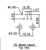
The bottom notch requires the socket to be positioned on the edge of the PCB, otherwise it would be impossible to release the plug.
My application requires the socket to be positioned within the boundaries of the PCB and therefore require the top notch connection socket.
I found the following with a top notch at http://uk.rs-online.com/web/p/rj11-connectors/7350282/ for which the following PCB layout applies:
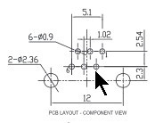
Any make with associated pcb layout would suffice as long as it has a top notch.
Hope I have made myself clear in answering your further questions.
Rgds
Dick
I see the problem, but the top notch one seems fairly different. The sparkfun version is on .1 in centers. The top notch one seem to be .1 in row but some odd value center (not 2.54 mm but something smaller likely 1.69mm if I’m calculating correctly) which seems odd to me as I would expect all rh11s to have the same footprint. It should be easy enough to modify the sparkfun pcb svg to match this particular plug but I’m not sure that will apply to any others. A quick look at digikey indicates it is manufacturer specific. The first one I found (from pulse) matches this layout, the next one is different again from either this or sparkfun’s, how odd. If you are good with this particular layout I can modify the sparkfun pcb svg to match it I think. I see that there are also straight up (as opposed to 90 degree such as these are) plugs where the wire would go straight up from the surface of the board rather than parallel to the board, would that do you better perhaps? I expect connecting and disconnecting would be easier for the user if it is in the middle of the board somewhere (and probably their footprint is different yet again  ).
).
Peter
Hi Peter,
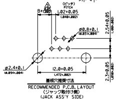
I could not agree more that there is no consistency in RJ through hole sockets PCB lay-outs. However, the Molex 6P6C Right Angle Through Hole RJ11 Socket would do just fine and can easily be obtained from RS components:
http://nl.rs-online.com/web/p/rj11-connectors/8006854/?searchTerm=8006854&relevancy-data=636F3D3126696E3D4931384E525353746F636B4E756D6265724D504E266C753D656E266D6D3D6D61746368616C6C26706D3D5E5C647B367D247C5E5C647B377D247C5E5C647B31307D2426706F3D313426736E3D592673743D52535F53544F434B5F4E554D4245522677633D4E4F4E45267573743D38303036383534267374613D3830303638353426
If the hyperlink gets across ok, than the pcb layout to allow modification of the sparkfun could be obtained from “Technische Documentation”:
Any assistance would be appreciated.
Rgds
Dick
OK, I think the pcb view on this one matches the Molex data sheet. Before cutting a board I would suggest printing out the footprint at 1 to 1 and putting a socket on it to make sure it is at least somewhat correct then check the gerbers carefully. Especially check the pin numbering as this one is the reverse of the sparkfun one which is I think (but may be wrong) what the data sheet called for. Breadboard and schematic are unchanged.
(edit: I screwed the pad spacing slightly, and have corrected it in this one, redownload if you have already grabbed this!)
(edit2:) Gak! found the pin numbers on the pulse part, and the original part is indeed backwards, yet another revision with the pins in hopefully the correct order, please redownload if you have grabbed either of the first two parts.
RJ11 Jack_top.fzpz (8.2 KB)
Peter
Thanks a lot Peter. Will indeed first make a print-out to check the final result before committing to fabrication. Again, thanks for yr usual help.
Hi Peter, finally managed to get the board prepared using the Molex RJ11 Jack_top. What I’m worried about is that pins of the jack are short circuit due to maybe too large soldering ring. I have attached the Gerber resulty as png file
. What’s your advice!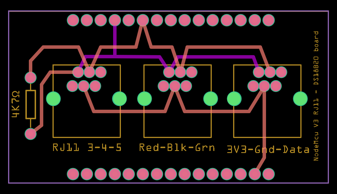
Let me poke at it a bit, I just copied the pad size from the sparkfun part (because the data sheet was silent on pad size) and it looks like the part I used has a smaller pin spacing (which I find odd and thus worth checking). If it looks right, I’ll reduce the size of the pad a bit. At present there is 8 thou clearance between the pads but that is a little small.
Peter
When I Gerbv it the mask overlaps, but the pads have a fine 7mil gap between them.
Try this one instead. I fixed a couple of problems, there was a translate in copper1 (which I just discovered a couple of days ago breaks putting the part on the bottom of the board), the holes were .040 where the datasheet wants .031 so I used the standard IC size of .035 and the pads were too close so I changed them to .068 (creating about twice the gap that it used to have at about 17 thou):
edit: updated the meta data so that it shows up in Inspector better (as type -top with its Molex part number). So you may want to redownload if you grabbed this already, although the only change is the metadata):
RJ11 Jack_top_fixed.fzpz (8.2 KB)
Peter
Peter, perfect! Many thanks 

Ready for production and logging pool temperatures using DS18B20 probes:

Rgds
Dick
Hi,
I have the same problem, but with the RJ11 connector of only 4 pins.
Here is the datasheet:
http://switches.in/downloads/Modular%20Jack%20616A%20detail%20Spec.pdf
Do you know if someone has corrected it too?
Thank you very much for your help.
Jhonny
While due to past laziness/ignorance on my part (requiring fixing of a number of internal errors), this took longer than it should have, this may do the job. The may in the above is because the data sheet isn’t clear whether the footprint is from the top (which I assumed) or the bottom. In addition it is different than the original Molex part and I would think they would all be the same. The bottom line here is you need to print out the footprint and compare it to a real part to make sure the pin numbers in Fritzing match the real part.
RJ11 Jack-4pos.fzpz (6.5 KB)
Peter