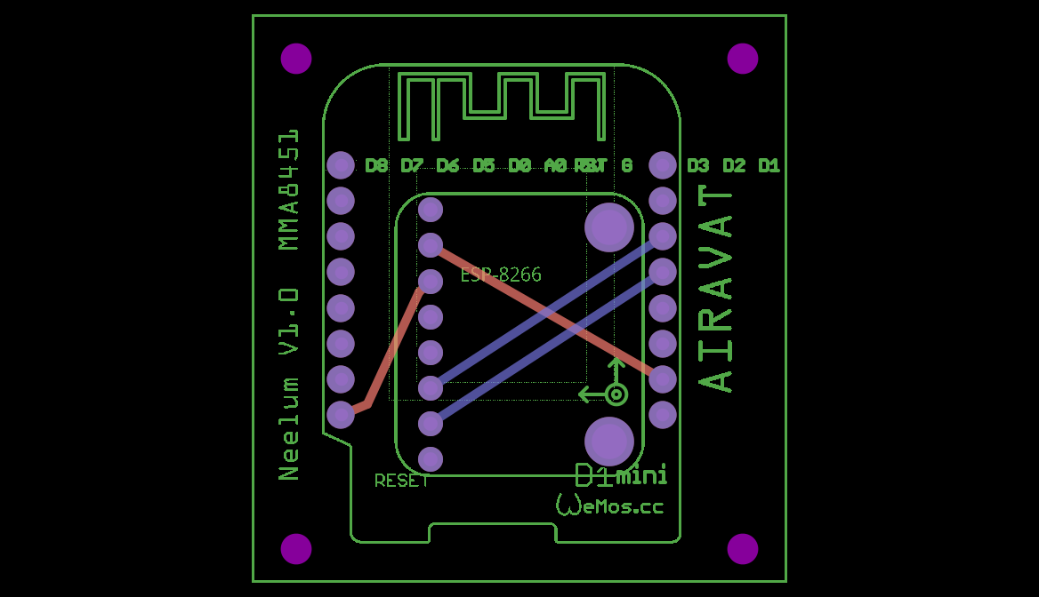
I am a newbie, and have created a rather simple circuit. Just powers a wemos mini d1 board, and then reads accelerometer data on I2C.
I want to keep the PCB size as small as possible. Reason, is this will be mounted in a cyclindrical pipe body, so best to be small.
Also, i plan to have a HEADER [male pins and female recep]. I want to solder this header to my custom PCB board. Then solder the accelrometer to PCB board.
Then i will press mount the Wemos [which will have male pins] on top of the Header’s female recep.
My question is: Does my PCB have all holes for the female header suitable for Wemos ? I cannot say, how many holes will i see once i order this.
I am expecting [or want] a total of 16 + 8 = 24 holes in my PCB. and 4 mounting holes on the corners.
Is there a software or tool, that tell me how my PCB will look like before i order it ?
I will be glad if someone took a shot at optimising this PCB based on best practices.
Thanks in advance.
I suspect for clearance reasons you are going to want the accellrometer board to be on the bottom of the board and the mini on the top of the board (or visa versa). So you want one of the other of them to be on the other side of the board. In Inspector the pcb layer setting will move one or the other to the bottom of the board. At present they are both on the top. Moving one to the bottom changes the trace routing which is why you need to do it now. I’d also suggest moving the accelrometer as far towards the bottom of the mini as you can (away from the antenna at the top of the board). It may interfere with the antenna and you can move it without incurring any more board room (the mini will be extending down that far anyway.)
It looks like it but the underlying parts aren’t the best. The holes are a little too large for .1 headers.
Yes. Export the gerber files from Fritzing
File->export->for production->Extender gerber
will export the board in gerber format.
the top of the drill.txt file that it generates tells me the drill holes are not right (they may however work):
; NON-PLATED HOLES START AT T1
; THROUGH (PLATED) HOLES START AT T100
M48
INCH
T1C0.086614
T100C0.036111
T101C0.039370
T102C0.098425
for .1 headers you want a drill hole of 0.038inches, the T100C0.036111 one will likely get rounded up to 0.038, but the T101C0.039370 one will round up to 0.042 very likely which is a bit large. This is a feature (or rather a misconfiguration) in the parts and can be fixed by fixing the parts. Displaying the files in a gerber viewer (this is from gerbv, a free gerber viewer from the geda project) of the complete board:
before ordering boards you should always look over the gerber files in a viewer. Sometimes it looks fine in Fritzing but has errors in the gerber output (and the gerber output is what you will get from the board house).
other than the hole sizes (which i will have a look at after I start another long running job in a while) it will work as is. Although I don’t often make boards, best practice says come out straight from the pad, bend at 45 degrees and go straight back in to the pad on the other end (with all bends at 45 degrees). That said at I2C speeds this will work just fine.
Thanks a bunch for your thoughts.
I did another example with MPU9250 part, and pushed it to bottom layer, while keeping wemos on top. I also installed Gerbv and checked all layers. It seems ok to my rookie eyes.
On the holes, i also checked the drill.txt. the max hole is 0.038. I am not sure how to change the hole size, although am puzzled why there are different hole sizes. I simply picked the board from parts list. Shouldn’t the software determine what size hole to put in pcb for those parts [pins]. I also reduced pcb size, as i want it as compact as it can be. Unless, there are any glaring mistakes, i plan to order this pcb. do you know when it might arrive in usa typically. [roughly 2-3 weeks ??] Any recommendations on how to order ? Fritz fab or some other places ?
The hole size is determined by what was drawn in the svg, and they are different sizes because there is no posted std so people draw what they like.
You usually go to the PCB manuf site and load the gerbers and get a quote. Note: It’s best to print out the design and see if parts fit on it before sending it out.
Looks fine to me too. I was fiddling with the parts last night, but downloads completed faster than I expected (and the parts are more broken than I expected too ). The Wemos one has translates in the pcb svg which is probably why the text is out of place (for me I would have deleted the text as it is adding unneeded clutter) and the hole sizes and pad sizes are wrong (with no documentation but word of mouth here in the forum that’s not a real surprise). The holes however look to be in the right place in the gerber and that’s what matters. being a couple of thou too big shouldn’t be a problem (too small which has also happened is a problem!) so I expect you are good to go. Eventually I hope we will be able to clean up core parts but it hasn’t even started yet.
i did notice the text being out of place. i tried to delete it, but the part was also getting deleted. so i compromised. i am gonna fish around a little bit more to see where else i can change any settings. but if there is a place i can fiddle to clean up the text that would be helpful.
Unfortunately that’s in the part as well. With the warning these are lightly tested, this pair has the holes at 0.038 and most of the translates in pcb removed. I tried to substitute them in your sketch and failed, and decided to fix the parts completely but I ran out of time. The mini has the text removed so you can put it in in the sketch if you need it (as is normally done).

 ). The Wemos one has translates in the pcb svg which is probably why the text is out of place (for me I would have deleted the text as it is adding unneeded clutter) and the hole sizes and pad sizes are wrong (with no documentation but word of mouth here in the forum that’s not a real surprise). The holes however look to be in the right place in the gerber and that’s what matters. being a couple of thou too big shouldn’t be a problem (too small which has also happened is a problem!) so I expect you are good to go. Eventually I hope we will be able to clean up core parts but it hasn’t even started yet.