A previous post got me thinking about a Grid on the PCB…
It’s useful (for me) to sometimes tweak the Grid in PCB view so as to better manipulate parts for alignment but, most often I leave the Grid turned off so I can force-fit parts and traces where I want them and use command-keys for Horiz/Vert alignment.
Adding to that, it’s very difficult to see the Grid on a PCB - perhaps it’s simply my computer display/contrast. But, I like the machine as-is.
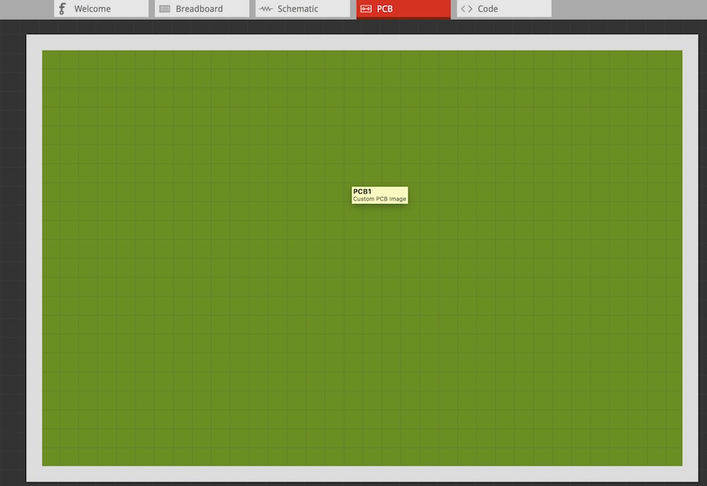
Thus, I made a PCB (call it a ‘Part’, if you want) with a Grid on the Silkscreen so, can hide it.
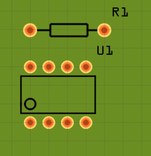
Grid spacing is 2.54mm (0.1 inch).
Image’s show alignment with parts/pitch and 90mmX60mm board.
The white boarder is for my ‘tooling’ keep-out area (where I use hold-downs or frame to lock PCB from moving when I CNC/Mill it…
Board file (Be Sure to delete the .fzz extension, added for posting the file)
PCB_90x60_wGrid_R0 copy.svg.fzz (11.8 KB)