PCB design CNC error 33 in UGS

Hi everybody,

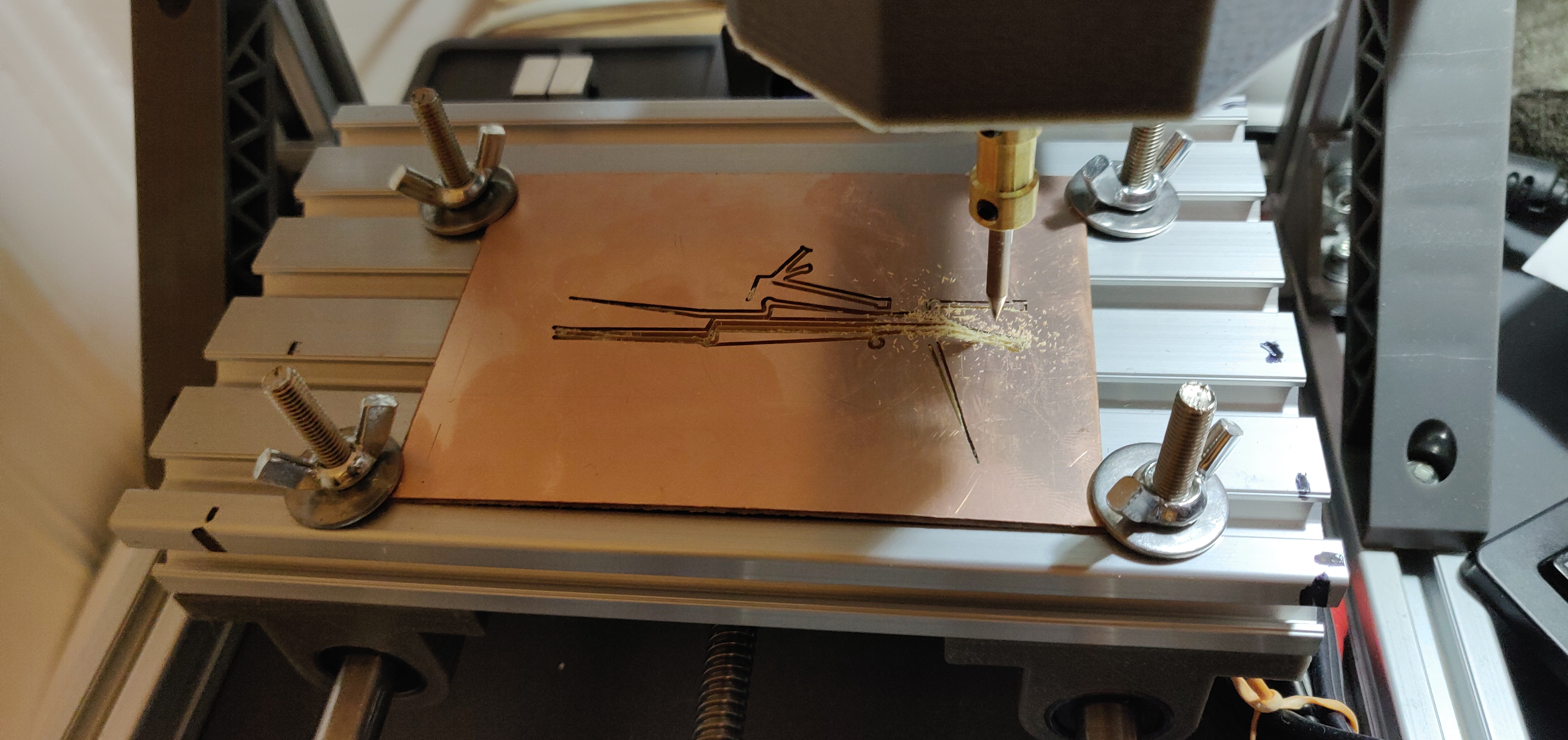
First post here, I created a pcb for a preamp. I used a process found on Instructables (link below) and have a lot of errors when I am trying to machine it. I am trying to find out if there is something wrong I did in the software, or something wrong with my cnc ( cheap 1610)

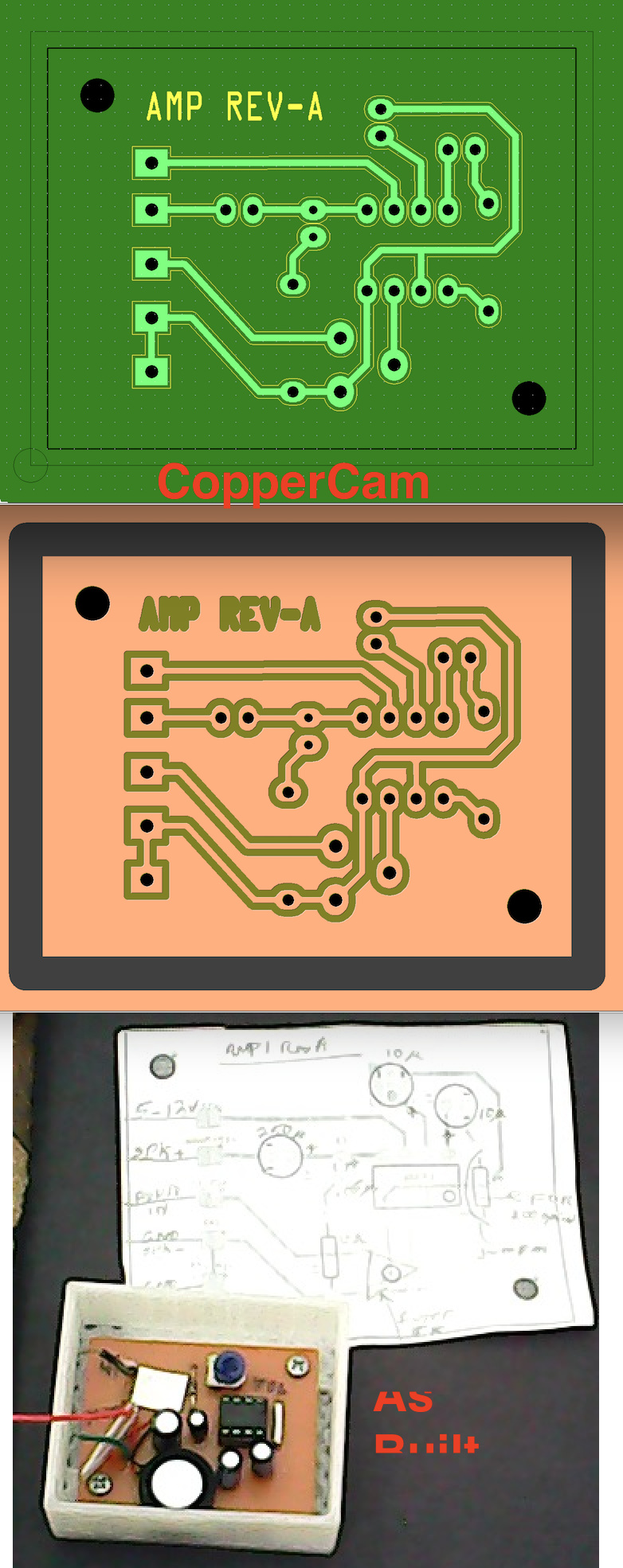
The first test with a simple circuit was fine only that the traces were to small.
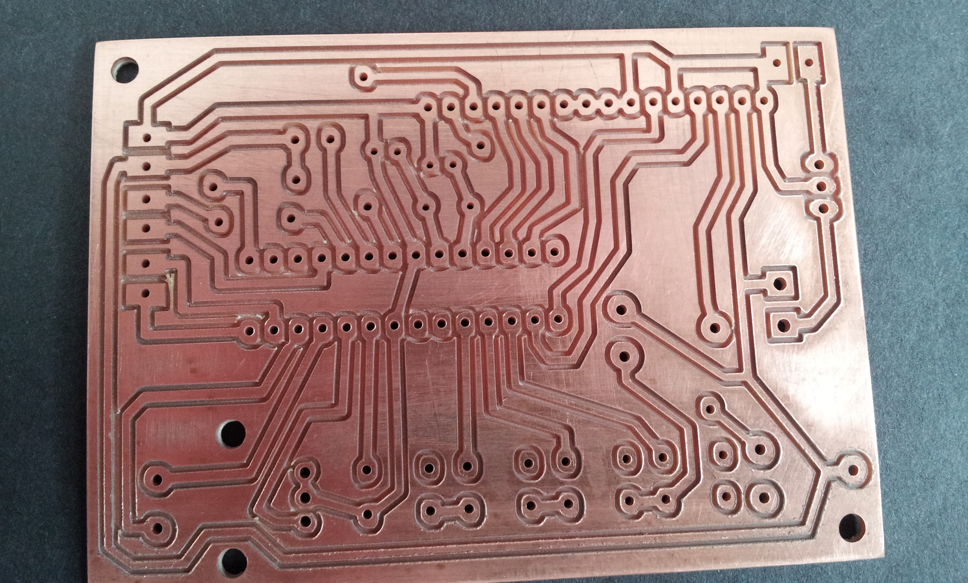
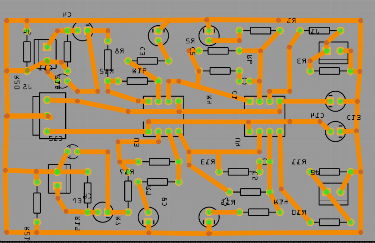
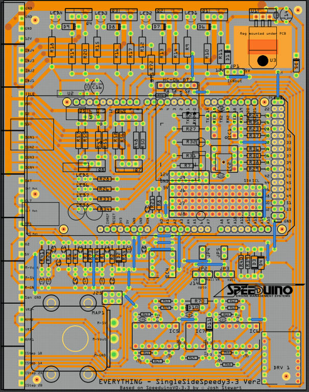
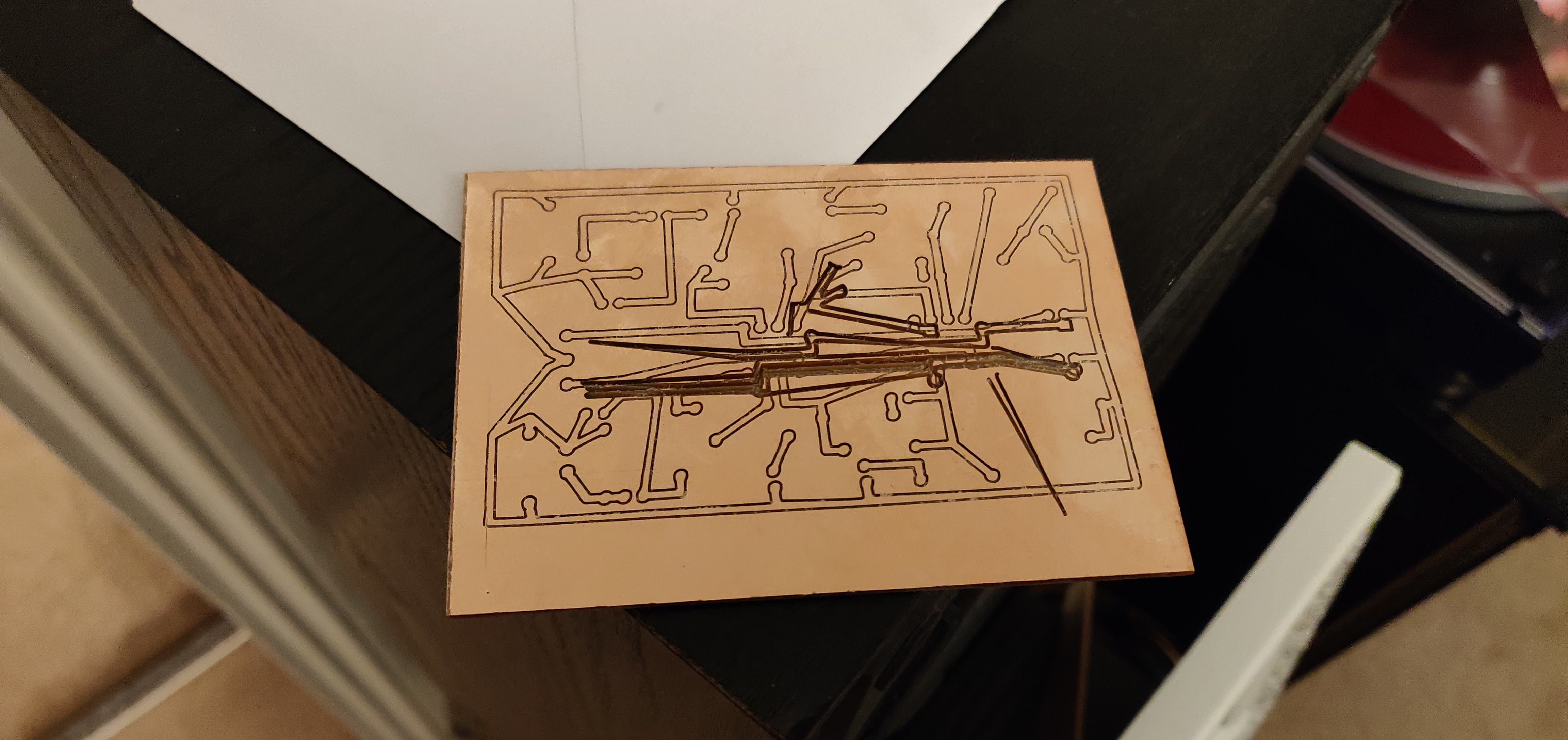
I designed the preamp pcb , exported , done all the steps, fire up the cnc and after it milled a few traces I realized that I forgot to enlarge the traces but the program seemed to run fine, re-done all traces extra-thick, and tried again. This time the machine would not follow the lines and I got a lot of lines with Error 33. I run the code on an online emulator and all seemed ok . I’ve been working on electronics for a long time but I am a beginner with cad and CNC. I understand the error is related to arches but everything else is above my knowledge now :slight_smile:

I can upload the code and pcb later today after I get home.

Thank you in advance

I make all my PCB’s on CNC mill. I’ll wait to see your files but, then will provides some tips that may help.

I generate the Gcode using CopperCam - you can download/try for free. The free trial is good for small boards (won’t reach the limit on small boards).

I would try Coppercam first as problem may be Makercam. I didn’t find anything that ran well on my Mac so, I use Virtualbox to run Window (and CopperCam). Example below…

While @opera_night is the expert here, it would be worthwhile for you to upload the .fzz file for your sketch (upload is 7th icon from the left in the reply menu) so we can make sure there isn’t a problem with the Fritzing sketch. You could also (if you haven’t already) do a gerber export and check the gerbers with a gerber viewer to make sure the sketch is fine.

Peter

A good Gerber viewer for Free is Cuprum

Hi guys,

I uploaded the fritzing file, g-code and a picture with what is milling now. The g-code is a text file with double extension as fzz. (don’t know if it works or if allowed, it was the first idea to upload the file)

Untitled Sketch.fzz (23.1 KB)


pcb.txt.fzz (169.6 KB)

I’ll look at your file. BUT, first!!!

The photo tells me the PCB is bowed. No wonder you’re having trace problems… read below…

See if the attached Gcodes will preview in CNC software. If good, do a dry-run (machining in ‘air’ above machine bed).

General Tips & Knowledge:
• Use either End-mill bit or V-bit
• Run at 8,000 RPM or higher (to avoid ragged edges)
• Use wide traces (milling depth affects width of trace: the deeper the bit goes, the narrower the resulting traces)
• Gerber files are not always transportable. The link to CopperCam’s page has Gerber file info on it that explains…

I use 24-mil trace width as default (set it in Fritzing. Also use 32-mil if/where needed)

I use 0.1mm V-bits but, I grind the tip to about 0.3mm.
I found that 0.5mm bits are too and results in traces too narrow when machine or board not perfectly setup.

I also use (and prefer) 0.8mm and 1.0mm End-mill bits for traces and 1/8inch End-mill bit for contouring and drilling big holes.

I assume your CNC is setup for minimal hysteresis and PCB mounting secures the board so it’s level. If not level, bit depth will differ at various locations and result in different trace widths (photo of one of my fixtures attached). It takes only a few mils of depth to affect the trace width). Thus, you can force width quality via adjusting depth on the machine - it’s a useful ‘tweak’

Audio Amplifier Example:
Attached is LM386 based amp I did for trying out various software packages before settling on CopperCam…

Fritzing File: AMP_audio_LM386_RevA.fzz (14.4 KB)

Gcode and CC File (zipped, (Be Sure to Delete the .fzz extension before un-zipping) : LM386_AMP.zip.fzz (26.8 KB)

drl_10.ncf = uses 1.0mm Drillbit
drl_12.ncf = uses 1.2mm Drillbit
drl_3175.ncf = uses 1/8inch Drillbit
Contour.ncf = uses 1/8 Endmill
engrave.ncf = uses 0.3V-bit
AMP_audio_LM386.pcb = the CopperCam file

Screenshot in CopperCam with Results. Click photo to expand and see all…

Fixture:

FYI - I briefly looked at the file - while it appears to be ok from a DRC check standpoint, it has problems from a design standpoint. Especially for an Audio amp. Always recommend Horizontal, Vertical and 45Deg angle traces for reduced EMI/Noise and better CNC machining.

Below is a quick (partially) tweaked photo of your board… Compare some of the traces to original… Several more traces should be tweaked…

FYI - These are the V-bits I use at Amazon

They’re low cost for 10 of them (versus sharpening more expensive bits…)

Yeah, try to avoid 90º bends.

Hi, thank you a lot for your help, the pcb is rough I admit , it is the proper circuit but I wanted to see how it mills before shaping it properly. I used coppercam and it worked well, now I have to play with copper cam to learn how to use it properly . It seemed the issue is was with maker cam.

Assuming you’re making a Single-Sided board (set to single side board and design on the Bottom layer in Fritzing).

In CopperCam you’ll need to Flip the board Horizontally.
The Holes are on their own layer as is the contour and traces/pads… When you Flip it, check the box to flip all layers…

Recommend also resetting Origin (that will be Origin/start point of Mill-bit).

You can totally resize and reshape the pads, singularly or many/all). You may want only a few sizes.

Can set all holes to same size to reduce changing bits as it will normally want to select bits corresponding to diameters Fritzing generated. The problem is Fritzing parts (designed by different folks) end up with different diameters.

For Pads too close, there’s a separator tool as well for traces…

When generating the Gcode, select the layer and bits. Do it separately for Contour, Holes, Engraving (engraving = traces).

Good luck…