The hole dia has to be big enough so that the blade/lug/pin of the jack can fit inside it. Basically the hole size will have to be at least the length of the slot. This were you need a vernier calliper.
If I keep the board the same with the traces how you helped me fix in the other post, you think it would be best to bring the Logic Ground traces to the top of the board? Then I would leave the Motor Ground traces on the bottom of the board?
I think if you just don’t give the logic ground ground fill seeds it will just appear as a standard set of traces and be isolated from the ground fill just as the trace on the bottom of the board is. That provides the best of both worlds. The ground fill gives the high current side a good ground and the logic ground attaches to the ground fill at the processor or the barrel jack and provides a separate low current ground path for the logic ground. You just need to make sure that the two grounds do connect to each other at one (and only one) point.
Using a via is a way of not having to fix the part. In this case there is a data sheet for the part on the Adafruit site here:
which says the pin is 1mm wide and has the x/y positions of the holes so I can check the alignment is correct. I don’t know why their suggested layout is so much larger than the pin size though. I’ll fix up the adafruit part to have a 0.042 hole (its easy) and post it in a bit. Even then, drilling the pads out and making sure that a 0.042 hole will fit the part is a good idea just in case their data sheet is wrong.
Edit:
Here is a corrected part. You will likely have to do a delete minus on the current part (which leaves the routing for the part intact but removes the part), restart Fritzing to delete the current part, then load the new part. Once that is done you need to move the two traces on the barrel jack so they connect up again and you should be good to go.
2.1mm DC Barrel Jack.fzpz (7.9 KB)
Peter
1 Like
I started reading these posts and my head started to spin… Perhaps too much morning coffee.
I didn’t read all the posts - forgive my intrusion into this.
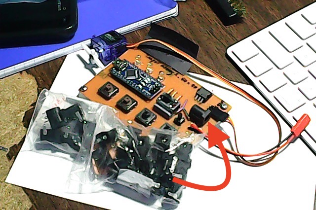
I use these barrel jacks so frequently that I have about 100 of them in my useless gizmo’s.
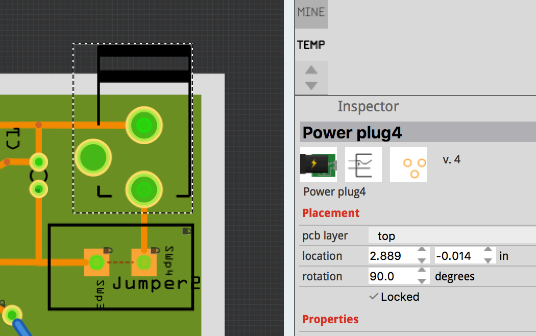
I simply use the Fritzing Part called “Power plug”. It has the correct size holes for the flat/wide pins (for soldering wires to them)…
Oh I see what you mean. Sorry, I’m slow with this stuff haha. To be honest I only need them a tad bigger and as long as it fits in the hole, even if its larger I would just need extra solder right?
To an extent, however solder isn’t a strong mechanical joint, so you want the hole to be close to the size of the pin that will fit in it (especially in this case where inserting the plug will put mechanical stress on the entire part. ) so the solder joint doesn’t break and cause a malfunction.
Peter
Haha, no not the coffee, my head is spinning too…mostly because I’m constantly confused.
I never saw this one! I’ve mostly searched for Barrel Jack, Power jack…So you’re saying this part will have holes large enough to fit most of the barrel jacks with the slot pins? Also, thank you!
Any chance you have thoughts on a ground fill vs having all my ground traces on the bottom? Currently,
Peter above helped me get my ground all sorted out and i have all traces on the bottom of the PCB with the Motor and Logic GRN separate. I added a Ground Fill before I got the PCB fab and didn’t understand why I couldn’t see the GND traces on the bottom of the board. Any idea on preference here since you seem to make lots of PCB’s?
Oh I missed this post. Awesome, thank you!
If I understand you correctly…leave the traces how you helped me straighten them out, clear the ground fill seeds, add the ground fill and the traces themselves act as the ground fill seeds?
That is how we have it set up correct?
The traces themselves will be the ground, the ground seeds will fill the rest of the board with the ground fill. What I’m not sure of is what will happen when the ground fill finds the traces that are part of the ground net. It may fill them in or it may (as I hope) leave them isolated because they don’t have ground seeds even though they are part of the ground net.
Peter
Ah I see. So I will manually set the Ground Fill Seeds for the Motor ground and NOT the Logic ground, then do a Ground fill on the bottom and hope for the best of both worlds?
Yep that’s what I’d hope. We will see if Fritzing agrees 
Peter
How will we know if Fritzing agrees? ![]()
If the logic ground traces appear on the bottom layer isolated from the ground fill but connected to the ground fill at the barrel jack then we have success and Fritzing is agreeable. The logic ground will run as it should with only a single connection to the high current ground.
Peter
Perhaps I’m doing it incorrectly, but none of the traces come through on the bottom. Even if I add the Ground fill and put zero Ground seeds the traces still don’t come through.
Unfortunately I can’t help here as I’ve never used ground fill. But with no ground fill seeds I’d expect the ground traces (all of them) to appear on the bottom layer with the fill only being where there are no traces. Hopefully someone familiar with ground fill can shed some light. I kind of expected it may not work if there is a ground fill seed present, because ground is all one net, but a straight fill I think should work.
Peter
A first observation about the Hole Diameter (for the part I referenced) is the holes are too big.
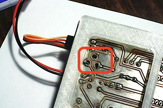
However, after installing many of them I came to this conclusion which, is best left to a “Picture is worth 1000 words”… See image… Bend the pin and Solder it…
[EDIT] The holes in the board below are a little larger than the ones the part makes (I simply used 1/8" drill bit instead of 1.2mm (I think that’s the actual dia).
So unless the hole is rectangular or, a series of connected round holes, the hole can be ‘almost’ as big as a doughnut since it’s the contacting face near the ring(pad) that is important…
Regarding grounds… I hesitate to jump-in to the fray so will add only this: Generally (unless a noisy design and/or radio or audio signals), ground planes are not needed - just provide proper grounding of components requiring special attention. Avoid ground loops…
Yes, I make many PCB’s and I prefer Single-Sided so, I squeeze my circuits to fit and use ‘Jumpers’ when needed.

Bags of these puppies
Yeah, for strength in the old days they used to bend the lugs right over 90º so they laid flat on the PCB. This would give it mechanical anchoring, plus large areas for solder to add more strength. I suppose you could do the same thing if you put a via down with a large ring, so that when the lugs were bent over it wouldn’t short with the GND.