OK manually editing svg and following @joneff advice:
the copper layer has to be described in the .svg with two nested tags like this
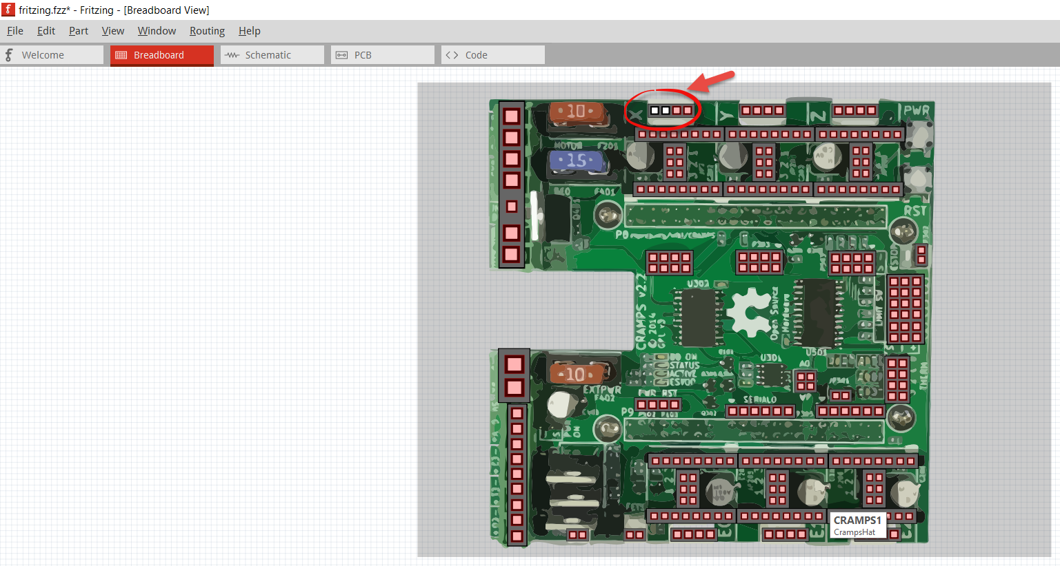
did the trick. PCB is populated now.[quote=“Old_Grey, post:20, topic:2542”]
need a whole series of videos, but this is a quick one to show some tips. This is not a proper guide, just methods to do stuff.
Ok, connector230pin was the only pin that was not connected to a pin in your breadboard.svg… although it does not seam to be all connect up right… Your schematic.svg had no schematic at all… it has the same image that is in your breadboard.svg… and the only thing that is in your pcb.svg is a resistor.
Now a strange thing - there are two connectors white in fritzing - and I cannot connect wire to it - what could be wrong?
In part editor both pins have check mark and select appropriate pin.
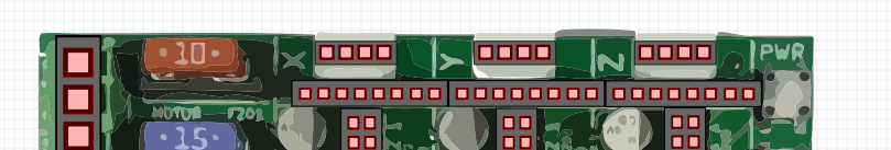
I’d say not a bad start for your first part. In the fpz from the part in the sketch you published above pin 0 and pin1 are incorrect in that they define connector0leg and connector1leg which define a bendable leg (and there isn’t a corresponding connection in the svg anyway). That will likely break 0 and 1 (your first two white pins) and a closer look at the image indicates that 2 and 3 are fine (have red connection marks) so removing the legId=“connector0leg” from the line (and the same in pin1) should fix that up.
p svgId=“connector0pin” legId=“connector0leg” layer=“breadboard”
Typically for a schematic view you would have a box with the various pins that you cam connect to showing. For a board like this you may not want to have a pcb view (it may not be that useful) but I don’t know how you specify that (although I know you can somehow).
That is a good question… that is connector0pin and connector1pin. In the Parts Editor, it shows them as connected and the .fzp and .svg are labeled correctly. must be something else going on.
All the pins in your breadboard.svg are embedded about 30 layers deep… one big mess…
Actually, a good place to start when making a part from scratch is with a generic connector. If I want a part with 50 pins, I will start with a 50 pins connector then all the .svg files will be all pre-labeled.
For future reference when posting a part for review it is best to right click on the part in the mine parts bin then click export file (which will create an fzpz file of only the part) rather than the full sketch (from which I did the above to get the fzpz file to play with).
That is because the original source was a png file that he converted to an svg with an online cloud service. In this case I think I’d do the same to avoid having to try and create a breadboard of a board that complex. The result doesn’t look half bad (other than the xml ) for not a huge amount of work. As I get further along I intend on remembering this trick for complex boards.
yes, you need to edit the fzp file for the part. You can get that either from the directory Fritzing stored it in or by exporting the part as noted above and either changing the fzpz file extension to .zip and unzipping it or (on windows anyway) use 7zip to unzip it directly. The non video howto posted above describes how to do this (I think both ways, but certainly with 7zip). it will likely have the filename
You could have just opened the .fzp from the /parts/user/ folder, edit and re-save it. Close Fritzing and reopen for the updates to be loaded back into FZ to take effect…
There are relays of various kinds around (someone just made a 4 pole double throw varient a while back). For the thcad I’d suggest starting with a generic IC of the appropriate pin size (looks to be something like 12 from the picture) and do as you did with this part to get the image (despite the ugly xml its easyest ).


 ).
). It could spare me some guessing