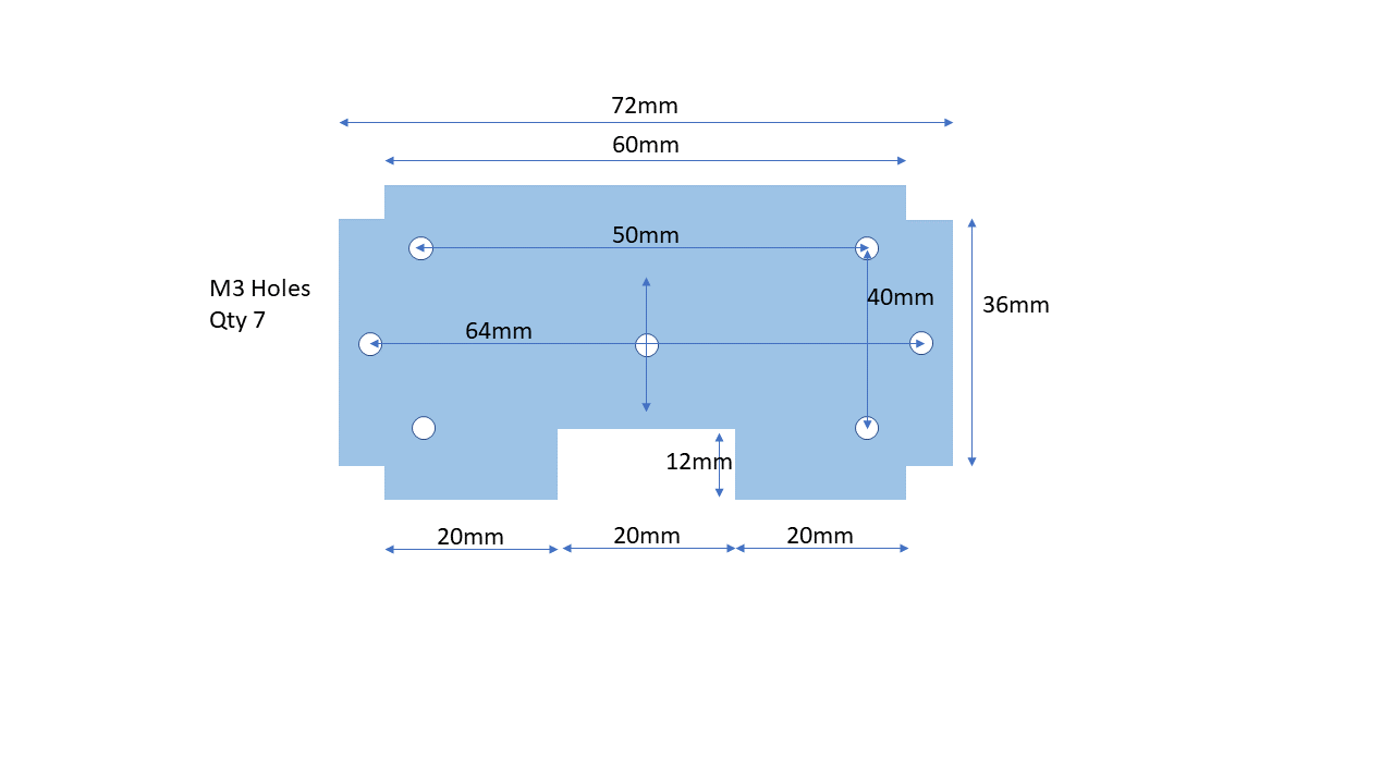
I spent a good amount of time trying to custom design a pcb that has holes and notches cut out.
Tried with inkscape and all, following some tutorials, and have not been successful.
Can someone please help me make this pcb as a fritzing part ? Thanks a bunch,
Note: There are a host of Drawing programs you can use; Inkscape, Gravit, Boxy, EZdraw… Paint, Draw, doodle… and many more.
However, all require knowing how to get what you want from them as they all do ‘it’ differently.
One useful program that does it without any issues (if not doing layers) is Open Office. It’s free and fully replaces MS Office. It contains a Drawing Program.
Silkscreen layers are default added in Fritzing so, no need to create your own unless you want a custom silkscreen. You can add graphics to the default silkscreen using the Part called “Silkscreen Image”, shown below.
The following Example uses OpenOffice(Drawing) to draw & export your (similar) shape, then is loaded into Friting…
Note: Line dimensions are shown at the bottom of the screen.