No problem, I’m retired and time is not an issue :-), thanks for the files, they have already been illuminating (and I have only started!). Looks like this is a fragile process, when I removed the translates from the not working svg (which is recoverable from the fzz file, I’ll write up how to do that later), it screws up big time:
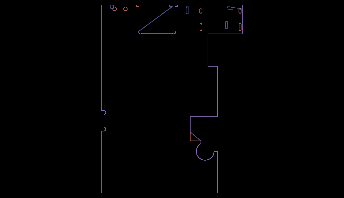
in this gerber output the purple lines are the non translated not working version (which displays correctly in Inkscape and Fritzing pcb view) and the orange is the working svg (without the translates removed.) I’ll have to look at the path in detail to see what is different. Meanwhile here are the two svgs recovered from the fzz file:
NotWorkingGerberExport.svg

WorkingGerberExport.svg

for any one else that would like to poke, the forum is happy with svgs today, so right click on the image and hit “save Image as” to save the svg. I’ll continue poking to see if I can figure out why there is such a difference in what should be identical xml. I still don’t know enough about creating paths to get this done successfully from scratch like you guys are able to, but at the moment I don’t need slots so that’s OK and I know who to ask if I do need slots ![]() .
.
Peter