Do you mean the USB connector end? If so that is easy to move without touching the pins … I just moved the USB connector and its associated parts down a bit so it is centered on the board as I expect it should be. I hadn’t noticed it was a little out til you mentioned it. Just selected the parts I wanted, grouped them then moved them down in y a bit.
Mainly the large 2560 chip, but yes other stuff as well.
Mine is the top one, but when the guy trimmed the top of it it offset some stuff. I eye-balled stuff until it looked like the pics on the net.
OK, I just updated the file yet again, I moved both the USB connector and the CPU chip to be centered. I don’t see why that will break parts editor but it may I suppose.
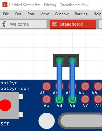
Please check all the bused pins are as they should be. In breadboard if you click on a pin all the other pins in the bus will light up yellow. I am assuming they were correct before I started changing things, but they may not be now .
thanks for that part. I like to make my own PCB, but i have the other Mega Pro Micro from robotdyn (with the button next to the USB Port). This PCB layout is not matching with the uploaded part here. Also i cannot find correct Fritzing PCB design for robodyn Mega Pro Mini.
Does anyone have the part design for the robodyn part?
Also tried to find the part discriped here in the project, but i can only find the robodyn parts in Ebay/Aliexpress.
Just so I’m clear, the button where the 6 pins on the top left are now and no usb connector? With the board a bit shorter that @Old_Grey referred to above? 52mm wide (there is also a 55mm one but it isn’t the mini.)? I t shouldn’t be a big deal to modify the current part to match. I’ll have a look at it.
edit:
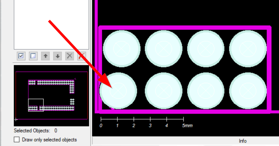
OK, here is a part that might work. You should print out the pcb section of this at 1:1 and compare it to a real board to make sure the pcb layout is in fact correct. Some of the bused pins may be wrong but that won’t affect usability.
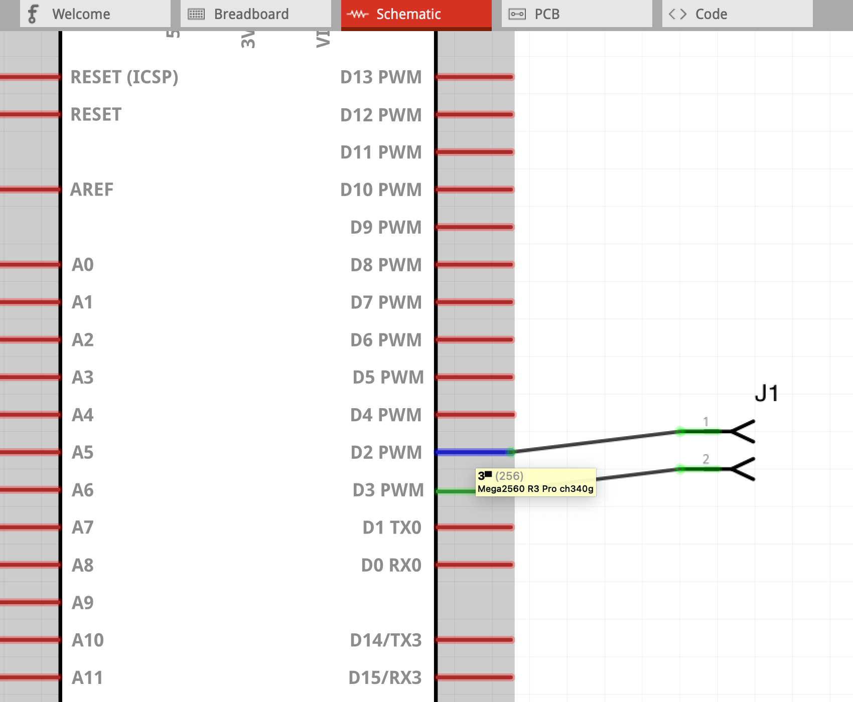
edit2 Mar 9 2021: Corrected pins D2 and D3 in schematic which were reversed in the original part, so schematic was wrong.)
thanks for that great job and this nice PCB Layout. Donation will be done the next minutes But i have another part. I think it is the 55mm one. I also think that is the most used one. Any chance to edit this?
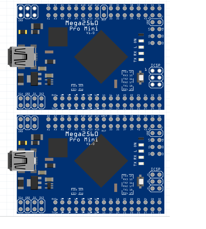
I think that is the correct one: (with Micro USB and 2 Voltage regulators)
Not a big problem, it is only a minor change to convert the pro mini in to this one (delete 6 pins, add the usb connector back in, add 2 power pins) to make one of these from the pro mini board (and we have a pro mini if someone else wants one.) Once you are used to making parts changing them is fairly easy.
edit Mar 9 2021: Corrected pins D2 and D3 in schematic which were reversed in the original part, so schematic was wrong.)
Thank you all for the files attached. Very much appreciated!
In the last file “Mega-pro-ch340g-ATmega2560.fzpz” I found an error with pins 2 and 3. They have been switched. They are correctly numbered (in text) in BB and PCB view but seem to have been switched in the schematic view.
Pins 2 and 3 have also been switched in the connector list in the parts editor. So pointing to pin 2 (written in text) appeared to be pin 3 (according to the on screen text box).
I have changed the pin assignment in the attached file, not the actual text in the schematic view.
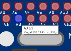
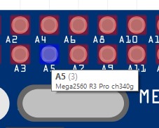
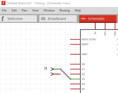
I`m not seeing the error. Assuming pin 2 refers to A3 in breadboard, that connects to A3 in schematic and A3 in pcb as does A5 (which would be pin 3):
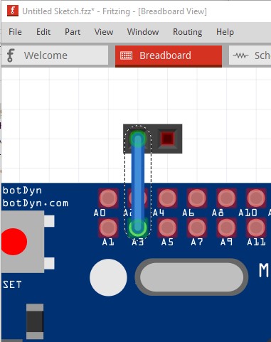
Connecting them to a 2 pin connector appears to work correctly (this is the original part file):
breadboard:
schematic:
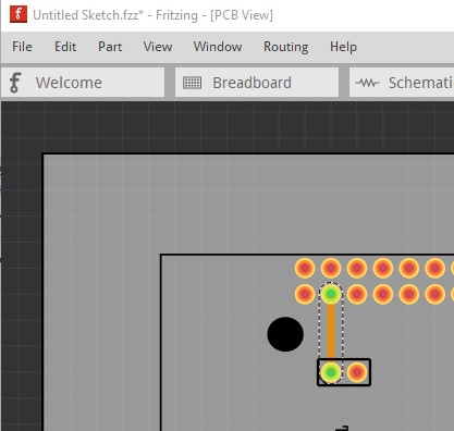
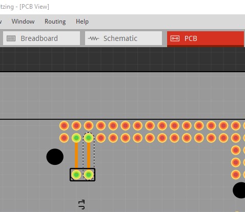
pcb
Same series with the second connection, all appears correct.
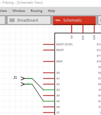
In schematic, the dual row connector alternates pins, so the A4 pin in schematic is actually on the top row of the connector not beside A3 as you may be expecting. I apparently did not include my usual graphic that indicates this, probably because I was fixing up an existing part.
Good catch! You are correct the pin labels in schematic (in all three parts) are reversed. I will replace all three with corrected versions in the original posts. To replace your part in a sketch, select the part then right click and click “delete minus”. That will delete the part but leave the connections in all three views. You then need to delete the current part from the mine parts bin (right click the part and click delete.) Unfortunately you need to close Fritzing to complete deleting the part, then restart Fritzing and load the new part from the post above. Drag the new part in to the sketch, then click on the end of each wire and move it til it connects to the pin it should connect to (and the connection changes from red to green.) Repeat for all wires in all views and you should be good to go!


 .
.