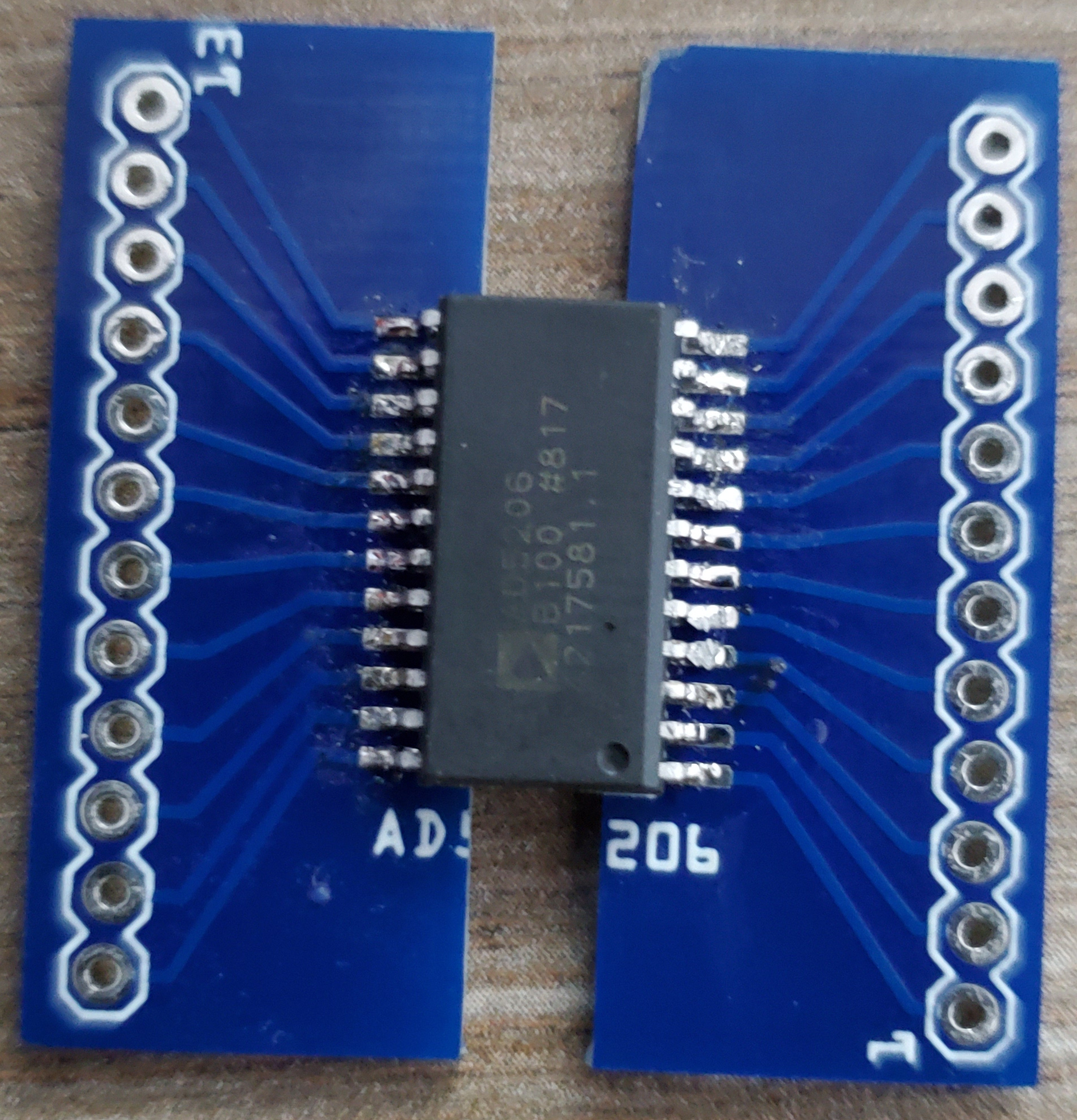
So I had my first PCB fabricated, a simple breakout board for the AD5206 digital potentiometer. I used a readily available Fritzing part that had an SMD variant, and I thought all was good. However, when both the chips and the PCBs arrived yesterday, I found that the chip is slightly wider than the part footprint on the board. (Reference photos below.)
The part footprint on the PCB has a spacing of 4mm between the pads, but the connectors on my chip have an inside spacing of 8.5mm. For the breakout board I was able to make it work by cutting the PCB in half; this is fine for breadboarding but I’ll need a correct footprint for the final product.
So my question is am I better off creating a variant of the existing part, making a new part from scratch, or editing and saving the existing part as a new one? I can’t devote a lot of time to this, only a handful of hours; I know there is a learning curve here, and have several tutorials at hand, but if there are shortcuts to accomplish I’d love to know. And finally if possible I’d like to be able to contribute my part back to the community, so I need to account for best practices and community guidelines.
My cheap trick for simulating a Part (this Post). Especially useful when time is limited and just need something that works.
For the Pads, grab the Part called “Pad”, you’ll need to copy&paste to get the quantity needed. Use the position -info at bottom of Fritzing GUI and the part/pad location box… [SEE EDIT BELOW]
You’ll need to use a Pin Header for the round pads. Basically, you’re not building a Part but, instead, adding stuff to the PCB that the ‘bare’ chip gets soldered to…
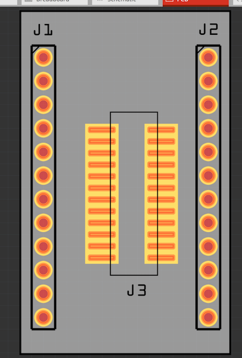
[EDIT] Took two minutes to put the attached together.
Used two Pin Headers with THT pads
Used one Pin Header with SMC pads.
I did not mess with the dimensions… etc. Load it and look at the Info for the SMC to ensure correct pitch… etc. Also Tweak the PCB as needed… and wire it up.
This isn’t an error (although there are a number in the AD5206 part in core). The chip is available in TSOP24 which is what the core part uses, and SOIPW24 (which looks to be what you have.) One solution is to change to the TSOP24 part and it should fit as is. Otherwise, as @opera_night suggested modifying the pads is a quick fix, but for me (probably not for you yet) it was pretty trivial to replace the pcb svg with a (fixed up, because the one in core is also broken) SOICW24 footprint, then change the fzp file to make it a new variant. That produces this:
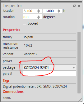
If you load this in to fritzing you will find that the AD5206 now has a new SOICW24 variant in Inspector which has (probably) the footprint you need:
along with the original 2 (24 dip and 24tsop which it calls incorrectly SO28 instead of tsop24). To replace your current part in your sketch, right click the AD5206 and click delete minus. This deletes the part but leaves the routed traces. Now select the AD5206 in your mine parts bin (which will be the SOICW24 variant) and drag it in to schematic (because of a Fritzing bug I haven’t found yet, the schematic image is randomly rotated if you drag it in to any other view) and place the part over the existing traces. Switching to pcb will give you a wider part. Now you need to grab the end of every connection in every view and move it back and forth until the connectors go from red (not connected) to green (connected) to install the new part. This is a pain, but usually less of a pain the rerouting much of your sketch.
Almost certainly doing what I did, Clone the part and replace the pcb footprint with a correct one, or modify the existing footprint to do what you need. That is less work than recreating all three views.
I appear to have elected myself somebody (as in somebody should make a better parts tutorial). I kept notes and svgs when I fixed up the s4a edu module for someone a while back and am using that to make a new parts making tutorial. Should be out soon for some value of soon .
Ball is in my court there too. I’m working on an upgrade to the parts checking script that will be added to the parts submit tool chain and complain and reject the part (with suggestions how to fix it where possible) if the part does not meet standards. It too should be soon, for some extended value of soon (I find parts making much easier and less frustrating then development, and tend to stop and make parts when frustrated by development )
Once that is finished the big job starts: cleaning up the current parts in core so they pass the check (many do not pass the current lighter test script). That will be a substantial amount of work, since the parts all need to be obsoleted, and the obsoleting mechanism is, AFAIK undocumented (another thing on my list to do, it is a very long list .) So more people willing and able to help will be welcome.