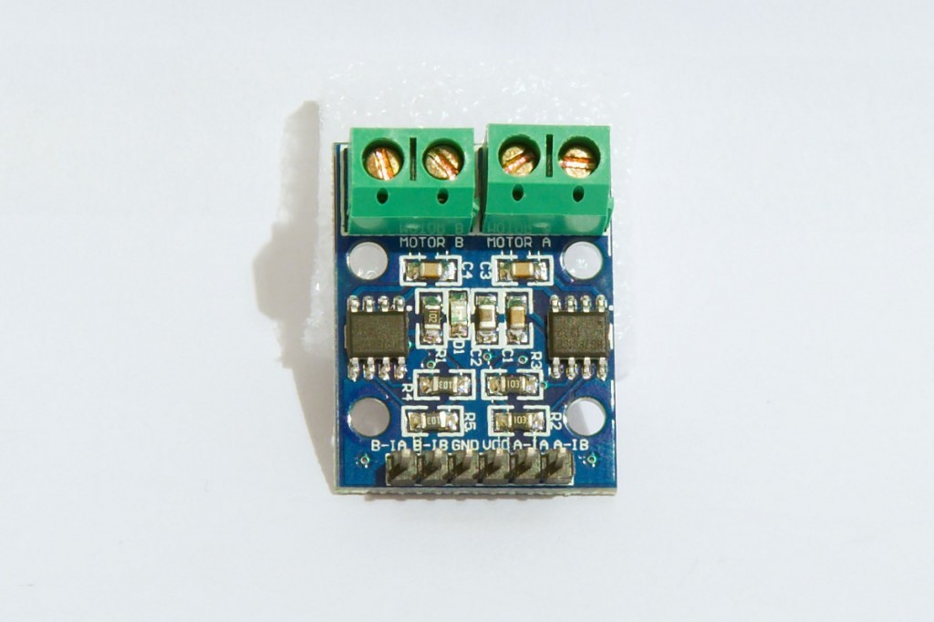
L9110 H-bridge module
L9110 H-bridge module.fzpz (38.2 KB)
1 Like
Pretty good.
For next time, in SCH you will notice some wires snap to centres of pins, and in PCB the pins aren’t assigned and it could probably use an outline.
Keep hacking FZ could use more parts 
I’ll try to fix the connection between pins a wires.
Regarding non assigned pins, those two pins are terminal clamps, not connected to the PCB. How do I assigne them, so that they aren’t depicted on the PCB view?
I used to know how to do it, but I’ve forgotten.
Search “Camden” 5.08mm screw terminals, and see how they did them.
EDIT
I think it might be a label in the .fzp file.
EDIT2
I think it’s this hybrid in the .fzp/.xml file
<p svgId="connector2pin" layer="unknown" hybrid="yes"/>You have a variety of problems, missing terminal definitions mostly, as usual it was easier to fix them than try and explain how to fix it (although I also don’t know how to fix it so it is happy with the screw terminals). This version is a better place to start. The broad outline of the changes is that I ungrouped everything in both breadboard and schematic views (many many nested unused groups) then in schematic cleaned out anything that wasn’t an in use connector or a line on the drawing (there are a bunch of unused connectors in there that don’t hurt anything necessarily but are messy). I also changed all the connectors from the 0 width (that are invisible in Inkscape) to .01 by .01 (so they will appear when selected). Then (after I discovered Inkscape 9.2 appears to be a bad idea!) I adjusted the box in schematic to center the pins better and added the missing terminal definitions. Same with breadboard. Then edited the fpz and cleaned it up (tried omitting the unwanted pins in pcb view but that doesn’t seem to help) . The pins connecting in the center was because you didn’t have terminals defined (without a terminal the connection is the center of the pin). Comparing the files in this one to your original should tell you all that I changed (if not feel free to ask here  ).
).
Peter
L9110 H-bridge module_fixed.fzpz (20.0 KB)
That said, this is the same file that I edited last night using Inkscape.92. Note that schematic is not only misaligned to the grid but scaled wrong in schematic (the pins aren’t on .1 centers). The file above was redone after downgrading to Inkscape.91 again. Unless someone can point out something I’m doing wrong I assume the change to 93 pixels per inch on Inkscape.92 is the cause of the change. The schematic modified with .92 exhibits the same offset that Fritzing sees when loaded in to .91 (scaled a bit bigger than .1 which would be explained by the px change) but displays correctly as aligned to .1 centers when displayed in .92.
L9110 H-bridge module_fixed_92.fzpz (26.3 KB)
1 Like