Sup fam,
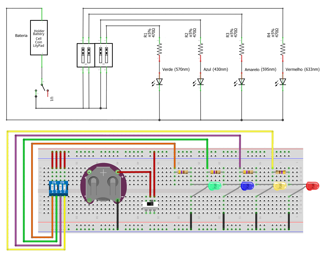
I am starting this thread to remind some of you to always check the diagrams in the forum before building them. I found this one while I was doing a lab experiment. The professor showed it to us and I thought I should share. This is what he gave us: http://fritzing.org/projects/control-leds-with-dip-switch
The problem is the way the reszistors are connected to the LEDs. They should be in series with them and the way they are would eventually burn the diodes. Here it is how it should be:
Yeah, it’s a wild world with open source free stuff.
Like any free EDA without strict part submission checking shouldn’t be trusted either - that includes FZ -, so any PCB made with them should be thoroughly checked, ie print out the PCB and test if parts fit on top of their pictures, and gerber checking, before getting them made.
By the way your resistors aren’t connected to the LEDs in SCH because there is red connectors, this may make an incorrect PCB. Also some junctions aren’t made properly. The small junction dots probably mean there is traces on traces.
Don’t sweat it, because everyone does that when they start. There are so many tips and tricks that I was thinking about making a tutorial vid about it. Like did you know clicking on a part pin will make things anything connected to it turn yellow. Be careful with diodes in FZ because the SCH symbol has a line through the centre that can hide ratsnest lines and traces under it.