Hi, please could i ask you
- why my part is normal colour in part editor but in red colour in normal fritzing.
- why wires jump from pins to center when i set them.
thank you !!
Hi, please could i ask you
Your part has an error in its connectors. If you post the .fzpz file of the part show above via the upload icon (7th from the left in the reply tool bar) I’ll have a look at whats wrong. You could also load the part in the parts editor and check all the connections are correctly set.
Peter
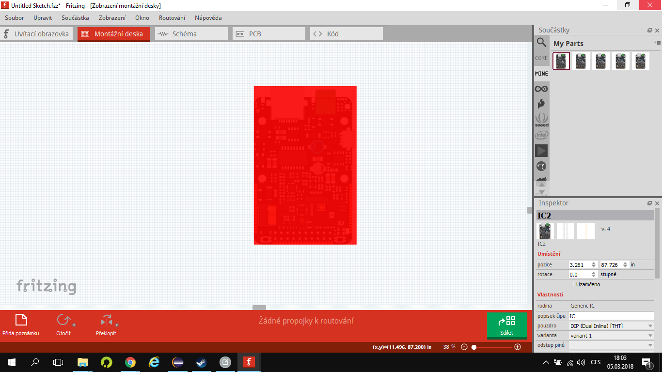
There are 6 unassigned pins in BB view, hence the red box. We’ll have to wait for Vanepp because there is a trick to having unassigned pins in one view that I don’t remember.
As Old_Grey said you have pins in breadboard unassigned although I don’t think it is intentional. Although they say there are tech documents on github neither I nor google can find them. If you have a pointer to the pin out for this board I can give you more than this general advise. Your Fritzing part has 60 pins defined, but the board only appears to have 54 pins. The problem in breadboard is that pin 53 to pin58 are unassigned (probably because they aren’t used) but are assigned in schematic. That is the cause of the red square. Your pin numbers are arranged oddly as well. Pin 0 is 4 pins from the right on the bottom connector, I would expect it to be at the top left or top right and go in sequence. It is possible this is how they have done their board (without a pin drawing I can’t say).
In breadboard pin1 and 59 are the same pin (which is likely wrong). For schematic you don’t want or need 60 pins, only 54 (0 through 53) unless there are connectors I’m not aware of.While I could fix this up to at least work, I think it will be easier to wait to get a link to the data sheet or pin out diagram for the board and make corrections from there. For schematic I’d arrange it to look similar to the board in breadboard:
1 ---------------- 54
2
…
16 --------------- 37
17 ... 36
which I can arrange to do for you if you like (and supply a pin diagram).
For PCB we usually do an outline of the board on silkscreen (so someone using it knows how much space it will take on the board) and put the pins in the correct place to match the connections (in this case you may want to do SMD pads as I think this is intended to mount to a board SMD). We can show you or assist you in doing those things if we have mechanical drawings for the board. You are mostly there no just some connector problems. Nice job on breadboard view!
Peter
I was thinking the extra pins are a program header, so not needed.
You are right about the PCB view, it looks like it’s has those half circle pads that they use to solder small SMD boards on bigger boards.
You are right about in not being labeled, I don’t even know what to search.
IODAG3E it is an open source IOT development board, I think fairly new. This may be the folks that make it trying to get a Fritzing part together. If so more the power to them, its win-win, they sell boards we get more people using Fritzing and both profit.
Peter
Thank you very much , now my part work perfect !!
I already have PCB schematic so tomorrow i will work on schematic and PCB visual of the IODA. Thanks a lot !!
When it will be done i will post it there…
M.K