Sounds to me like:
- Very simple to solve
- Difficult to solve without parts on desk
- Mixture of Parts and Codes and skill/knowledge
However, I’ll say this:
Although Coding can be confusing (esp for newbie) it isn’t difficult to move forward if a plan is in place.
So, though most of what we’ve been going over and will come up is better suited for, perhaps the Arduino site (or other), I’m happy to respond here as it enables providing some usable Fritzing files for testing.
That said, consider this as a Plan:
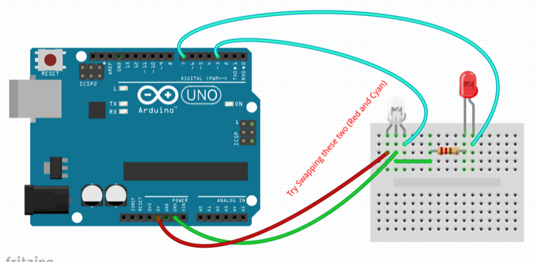
Grab these parts:
• UNO
• LED
• Resistor (100 to 330 ohms, approx range)
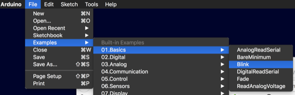
In Arduino, Load an Example Blink sketch.
This sketch does NOT use additional parts listed above.
I simply used the LED on the UNO.
You will understand how to set it for displaying (On/Off).
The comments in Code are useful and there is a link…
Once successful, now Tweak the Code lines where it says "LED_BUILTIN " Three places to change it.
Replace them with the simple number 13.
The Same LED on UNO should blink as before.
What did we do? The code has LED_BUILTIN hard coded to pin D13 in Arduino.
All we did was to Hand code it instead.
So, when someone say’s change the pin to D5, you look at your code, find all the places where what you want to change is located and, simply change them to 5. Note, depending code, IDE version…etc, You may also be able to use D5 instead of just 5
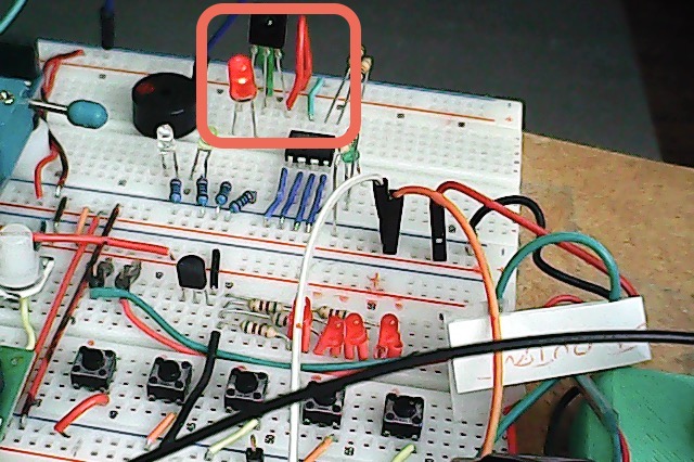
Now, install the Resistor: One leg to GND, the Cathode (short leg with little Flat edge on Plastic rim on LED.
Attach the Anode long leg) to whatever pin you want (don’t use D13. Though you could, let’s not complicate it).
Change the Code to reflect the desired Pin.
Compile and you should see it blink instead of the LED on the UNO.
Now, going back to Codes I posted…
For testing, you have a choice:
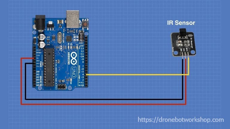
Use Digital pin or Analog pin.
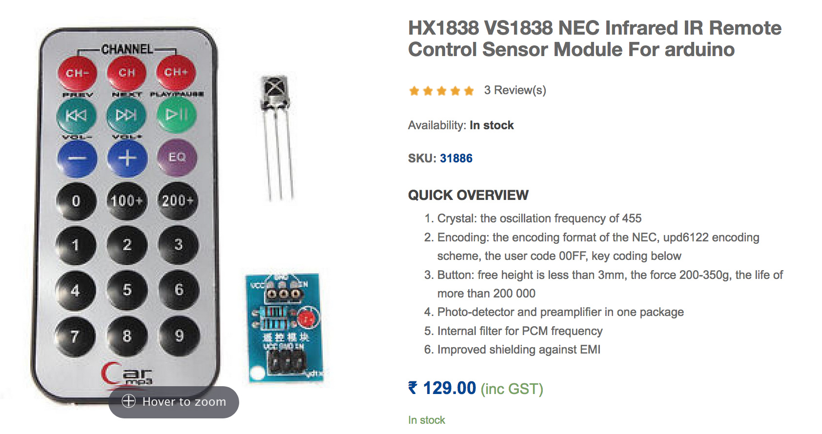
Since your IR has a preAmp, it can put out a signal level high enough to flip.
For Digital test use whatever Digital pin you want but ensure you change the code to call out the same pin number.
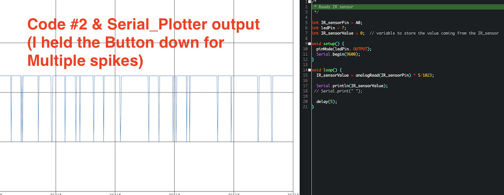
For Analog test use an Analog pin and ensure code calls the same number.
There are other Example codes to explore…
Once certain that Blinking happens with LED and gained knowledge of above, working on the IR will be easier to solve as ‘we’ will have a foundation of events that clearly form the basis of this stuff.
The Next step, however, would be to implement a Button to press and cause the LED to blink. Then, it’s little more than hooking up and clear coding the events… The IR receiver is simply much like a Button press…
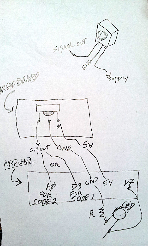
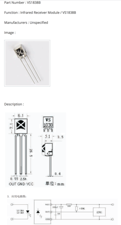
 I took a look around the Net and find similar Ir sensors. But, some have different pinout’s versus mine. I googled the spec for HX1838 and finally found a spec - image of pinouts attached.
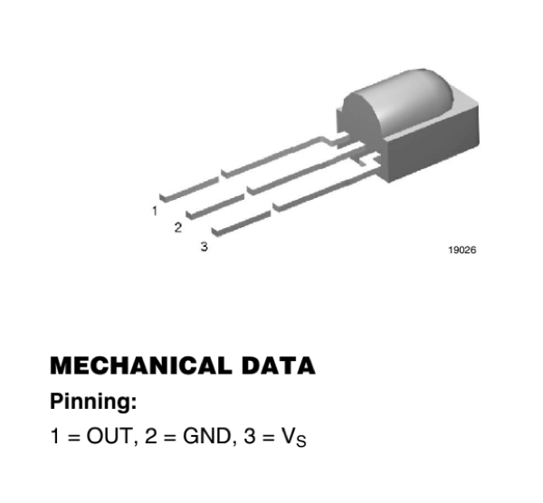
 ). A quick google search doesn’t turn up anything likely though, although my search term may be wrong as this should be a common need for folks without a scope.