Hello everyone,
I am French and I am a beginner on Fritzing as well as on this forum.
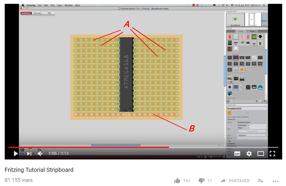
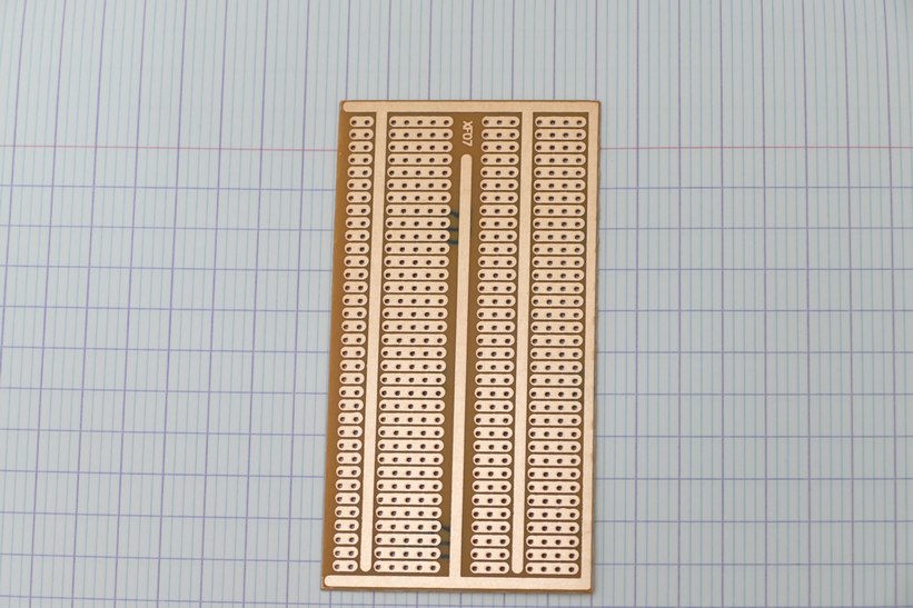
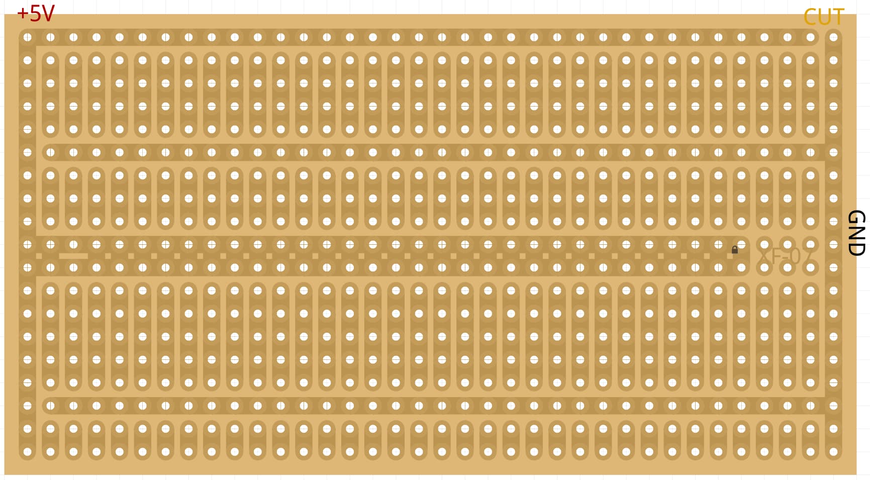
I wish I could create a stripboard like the one visible in this photo :
(I have many breadboards like this one)
I have watched this video several times, but I do not understand how the guy came to create this streapboard on Fritzing :
Is it possible ? If yes, how ?
Thank you for your help
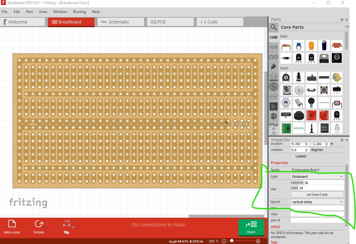
If you start Frtizing and in the parts bin (the window on the right) scroll down to breadboard view the third icon from the left is strip board. If you drag a copy of that in to breadboard view you will get the default vertical column strip board. Now if you go to the inspector window (bottom right) and select board layout then in the pull down menu select Radio Shack 276-150 you get the closest standard perfboard that Fritizing has. To get your exact perfboard (and I expect what the person in the video did, although the download site in the video didn’t work for me) either you or one of us would need to make a custom part that matched your stripboard. If you can make the download site in the video work then download the .fzz files and use file open to load them in to Fritzing and see if one of the boards he has matches yours.
Thank you for your answer Peter,
I found how to modify, cut or add tracks
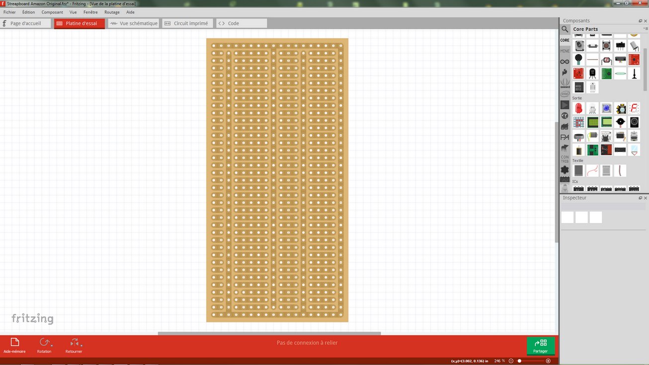
Tomorow i will post a screenshot of my work.
(For me , the links of vidéo are also broken)
Please, another question:
I think it’s the printed circuit board that we see, so how to display the streapboard components side in Fritzing ?
Unfortunately you can’t in breadboard. To view both sides you need to do it in pcb view (and the strip boards aren’t created there so you have to create them), breadboard only shows the view from above.
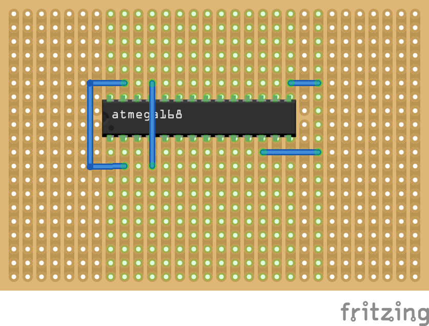
Yes that looks to be correct in this case (although this strip board looks to be a custom part to do that, the standard strip board won’t do this). There aren’t actually two layers in the drawing, a wire connected to the B strip in breadboard will be the same as a wire connected to an A strip, the different color of the trace is the only difference that makes it appear to be two layers, Fritzing only recognizes one layer in breadboard. Perhaps I misunderstand what you want to do, but in breadboard you can only look down from the top of the board (I had assumed you wanted to flip the board so you are looking at the bottom side which Fritzing won’t do.) The board above appears to have been created as a custom part with a different color used for the bottom layer on one strip. It isn’t clear to me why you would want to do this because you can’t see or connect to the bottom pads (assuming they are there) under the IC. Wires (in breadboard) will only connect on the top of the board like this:
You can’t run the wires under the chip or flip the board to see the wires on the bottom side of the board or have a different wire connect to the bottom of a board (Fritzing will connect it to the top layer, the only layer it recognizes).
Thank you for your explanation !
I wanted to be sure that when I put a component on the streapboard with Fritzing, it would be the same in reality with my plate. (That it would be well disposed)
Another small question:
are there smaller components or semi-transparent components that could be created for streapboard?
I’ve made some parts which are available here in the forums (I’ve been so far too lazy to submit them on github to get in to core parts) of parts that are shrunk for perf board use as have other people, what I didn’t do is keep a list of them, so you need to search. It is mostly LEDs, TO220 cases in various sizes. to92 transistors and capacitors so far I think. Most of mine have “top view” as a tag I think so searching for that may help. If you need something that isn’t done yet, post and I’ll look at how easy it is to do (it is usually not too bad if you are used to making Fritzing parts).
That original pic is of a very old version of Fritzing, and the darker greenish tracks “A” are indicating it’s connected to the IC. Not top/bottom. AFAIK all stripboards are single-sided on the bottom only, so no need to show tracks on the top.
You can make a stripboard in PCB, but it is a bit difficult. You set grid to 0.1", and use vias and linking traces. You can do small sections and duplicate them, but it is a bit tricky.
Not directly in breadboard. Inside Fritzing there are different svg (a graphic format) files for each view. Typically the ones used for breadboard have been made to look like the component tilted at about 45 degrees. As you have found this is inconvenient with strip board. Therefore for the parts I and others have made for top view for strip board we change the svg for breadboard to look more like the silkscreen in pcb view. Unfortunately it isn’t automatic, we need to create a new part then edit the breadboard svg file with an svg editor such as Inkscape to make the change. That is a fairly complex process until you get used to doing it so it is usually easier to get one of us to do it for you (although learning to make parts is a useful skill if you like Fritzing).
If you export this image as an SVG you could use it as a picture in PCB view. That would let you use PCB view but would not let you unlink the bars as they will only be a picture. You could just draw traces between the pins you want connected and those would let you know which bars to disconnect in real life.
After exporting the SVG you would crop the picture to be just the board. Then delete the original PCB in PCB view. After that find the PCB silkscreen image part in the core bin and place it in PCB view. Then in the inspector change the image to be the image you cropped. After that set its origin to 0,0. Last thing is to make sure the grid size is set to 0.1" (2.54mm) and that snap to grid is turned on.
Thank you for your answers to both, Peter and sublimeartistry.
It’s very kind of you to give me ideas and proposals but it’s too difficult for me.
There is very little French tutorials about Fritzing and I understand not very much English language.
Sorry, but I’ll settle for that, never mind!
Google translate can sometimes help with translations (we often use it to answer questions in other languages). In any case if you have more questions or need help feel free to ask and we will answer as best we can.
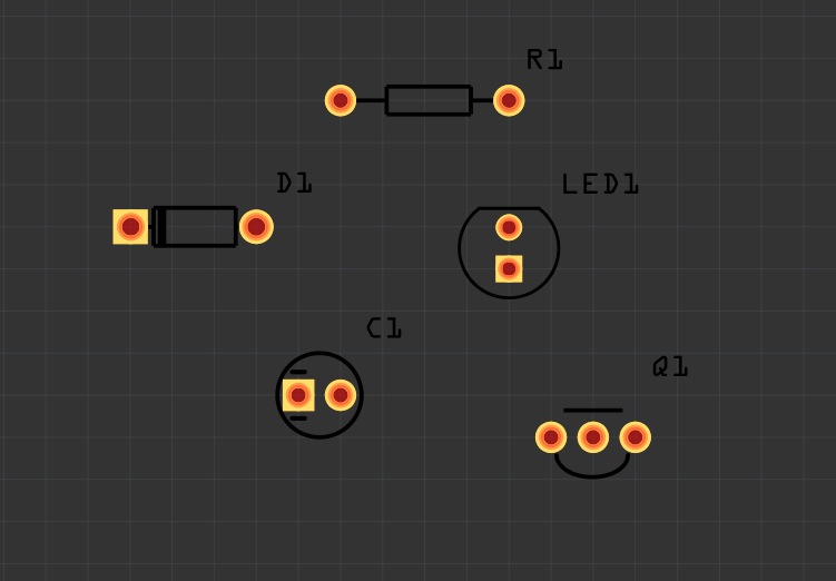
I just wanted to add my re-creation of this XF-07 (XF07) stripboard: Stripboard XF07.fzz (3.0 KB)
Important notes:
I mirrored the layout (just as gemini07 did), because you are looking from the top “through the board”. So keep that in mind when soldering
The central line (next to the XF-07 text) is just one spacing wide, but is centred in a 2-spacing wide area. Therefore I chose to draw it two spacings wide (which fits better with pin spacings). Keep that in mind when designing your circuit.
Also there are no holes/solder areas around the text.
Some of the traces don’t have holes, but since I could not find a way to remove them, I left them. So be careful that you don’t plan any through-pins there!
I find it very useful to separate some of the traces and split it up into +V and GND, e.g. like this:
this will likely screw up as the code recreates the stripboard and likely won’t give you your original part back (because the code doesn’t know how to make it again.) but other than that good job!
vanepp, that’s true. It is not an elegant solution. But it seemed the easiest I could find to quickly get the result I wanted. It still take 10-15minutes to do, so I thought I save others the trouble
With that being said: I feel like Fritzing could benefit from more stripboard presets. Do you have a primer on how to make them?
Unfortunately no. They are created on the fly be code in Fritzing so you would need to find and modify the appropriate source code which is usually a very difficult task (as the source is mostly completely undocumented!)
edit:
I am (slowly!) working on a python replacement for the parts factory (which creates headers and generic ICs and probably stripboards too) which will make this easier but it is going slowly (as I’m not a particularly good developer )
edit1:
Sometimes I forget what I have done. There is indeed instructions (fairly complex though) on making a custom part that is a strip board here