Hi
I’m a newbie Fritzing user. I have very basic questions related to schematics and using Fritzing software.
Is there any hidden connection like global labels. It’s hard and confusing to connect every single wire.
Are there any shortcut key for move and rotate.
Best Regards.
Can you upload a sketch that illustrates your problem (upload the .fzz file via the 7th icon from the left on the reply menu)? While I’m not sure what you mean by hidden connections, if you make the circuit in breadboard view (as you would wire it in real life) when you switch to schematic view the connections will appear as rats nest lines. If you double click on the rats nest line in schematic it will connect to the next connection point. Now click on the wire and drag it to route it the way you want. Then move on to the next wire. If you like you can start in schematic and click on a connection (the red part of parts) and drag a wire to another component’s pin (again a red part). With a correct connection both pins should turn green. Again you can click on the wire and drag it to route it however you please. There isn’t any auto route function (not in breadboard or schematic anyway and autoroute in pcb works poorly).
To move something, click on it til it selects then drag it. To rotate a part click on a corner until the arrow cursur turns in to a 1/4 circle with two arrows then click and drag the part to rotate it where you wish.
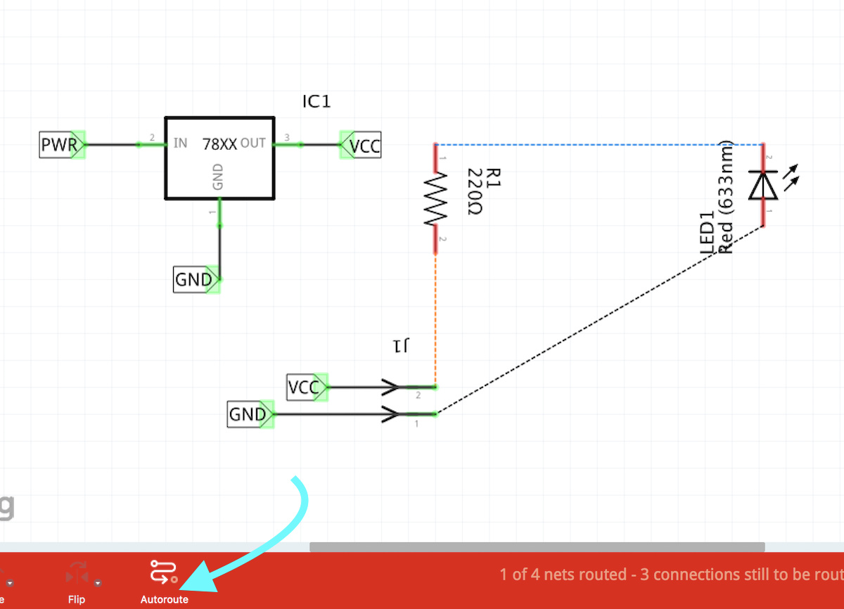
There is Autoroute in both Schematic and PCB (not in Breadboard).
They work independently (i.e., clicking in one panel does not autoroute in the other, must do separately).
Autoroute is very buggy - recommend not using…
Accessible from Menu and/or by clicking the Autoroute label at bottom.
This example also shows how to use the Part called “Net Label” for connections…
I use mostly Ubuntu Linux, I guess shortcuts not working with Linux.
For the hidden wires. I mean rats nest lines. Now It works, thanks. .
I just need to take bit space for a wire. If I take it too close it won’t connect.
Is there any library for test probes and 868mhz PCB antenna or any explanation on how to make your self a library.
I kinda like Fritzing software though. It’s very easy and compact. I just used 2 times and I made my own PCB
As far as I know the shortcuts should work on Linux the same as windows. What are you trying to use that doesn’t work?
Yes connections are a bit picky, the best bet is to make sure the connection goes green, but clicking on a pin will light up everything that is connected to it yellow so it is a good practice to check that everything you think is connected lights up yellow if you click on a pin in the net. The other thing to note is it is best to complete one view completely then use the rats nest lines in the other views to complete them. If you make conflicting connections in two views, for example with two resistors connecting pin 1 to pin 1 in breadboard but pin 1 to pin 2 in schematic,you will cause a short across the resistor and worse Fritzing may not be able to recover the routing database even after you remove the short sometimes meaning you need to start again from scratch.
I’m not sure what you mean by test probe, but in general to find parts a google search for “fritzing part test probe” may turn up something someone else has made. If you have a data sheet for what you want , if you post a link to it I will look around. Fir the antenna there is an example for a 2.4ghz antenna here:
and I remember (but can’t immediately find) a post with 3 or 4 different directional antenna parts. Again a google search for fritzing part antenna may turn up more examples. Note Fritzing can only do 2 layer boards and some of the antennas need a 4 layer board I think.
Making parts is fairly complicated and poorly documented so you are probably best off asking for help in here (posting the part you are working on works best so we can see the xml and svg files). That said these two tutorials apply to the current version of Fritzing (most of the others are for earlier versions and may no longer apply). Old_Grey’s video series is the most complete:
While I’m not sure without looking at the source, I suspect the shortcut keys are hard coded and thus need a code change. Someone else may know a trick though.
That is one option (and the usual suggestion in Fritzing), but if you want breadboard for a tutorial for instance and would really like to show the probes, it is easy enough for me to make a custom part that illustrates test probes (it is a cosmetic change in the breadboard svg file of a two pin header). A couple of us made a ph probe for someone that wanted to do just that and this would be easier (parts making is fairly complex, so it is likely easier for me to do it than you).
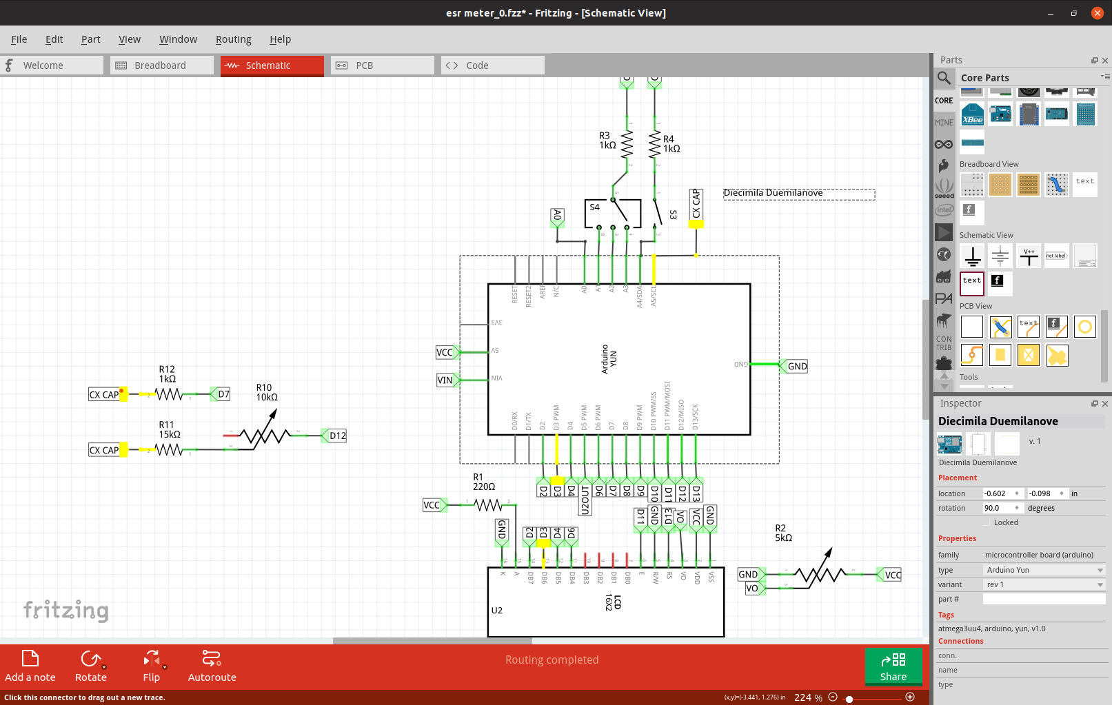
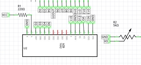
Unfortunately my first guess is data base corruption due to a connection error that wasn’t reversible. If you post the sketch (the .fzz file, via the 7th icon from the left on the reply menu) I’ll have a look and see if I can fix it. One thing I see is unless the yellow square is covering a character, r11 and r12 have the same label and will cause a short.
Since it really is fairly trivial to make a new part, here is a part for a pair of test probes more or less life size in breadboard (about 4 inches long). To load it, download the .fzpz file, then in Fritzing file->open , navigate to where the .fzpz file is select it and click ok. The new part will appear in yout mine parts bin ready for use. The connections in breadboard are on the end of the lead wires where they would plug in to the meter (I was too lazy to put banana jacks on the end ).
 .
.