Thanks again for all the help with the two boards I have been working on. I think I am ready to order, and will be using Fritzing. The seamless process is worth the time in shipping. I have looked at the image files that they create for silk screen, drill holes and copper top and bottom traces. It seems that all holes are plated through … as I would want.
Final thoughts about the additions I have made, and a question about using mini contactors.
For background, the boards are for remote monitoring of an Aquaponics project. The remote sensors will be attached to the “stereo” plugs and may have 20 feet or so of 26 ga. 3 conductor stranded wire to put them in place. I have also added a second power jack to monitor the “native” power in the building and look for a power outage. The main power jack for the electronics will be plugged into a UPS to maintain internet connectivity.
I chose to use two mini contactors (Omron G5V-1) … one to sense the power failure by “releasing” a set of contacts which are normally held closed when power across the coil is present. I have added a resistor to the 5VDC power source because the coil amperage rating is 30ma and the “wall wart” power supply by default is 2000ma … and I added a second resister to drop the 5 VDC to 3 VDC so I would not overpower the digital input pin (D8). Have not calculated the size resistor needed
, but I think using Ohms law, I can figure that out (hopefully).
The second mini contactor is used to sound a buzzer … again when some condition exists that would need notification. I have used D5 as the pin which I will set “high” to act as the trigger to energize the coil which powers the buzzer. I feel I can use this to sound the buzzer when any “digital read” condition is out of bounds. I felt that I should add a “pull down” resister to that pin (or perhaps in the code I could set that option).
I do not have a lot of experience with the need for diodes or capacitors and thank you all for you help and patience.
Attached are the Fritzing files as they exist now.
Hate to be donny downer but a few issues: you actually don’t need the mini contactor on the main board. It would have the same effect (and be easier) to connect the ground of the 2nd wall wart to system ground and the +5V lead to the top of a resistive divider that reduces the 5V to 3V (a little less than 3.3 for safety) and feed that to the digital input pin. When power is on the wall wart provides 5V and the digital input pin sees a high level (power on). If the power fails, the 5v drops to 0 and the digital input pin goes low indicating power failure. If you want to keep the contactor you don’t need the resistors to the wall wart. If the coil is connected directly across the 5V input from the wall wart it will take 30ma of current (the wall wart can supply up to an amp, but will only supply what the circuit wants, in this case 30ma. You should connect a 1n4001 diode in reverse (i.e. cathode to the 5V pin) across the coil / wall wart to absorb the inductive spike from the relay coil though. Without the relay a 100 ohm resistor one end on ground and the other on the digital input pin of the micro with a 68 ohm resistor to the +5V connection on the wall wart will draw about 29ma and supply 3v (with 5V in to the top of the 68 ohm resistor) to the digital input pin, enough to register as high (>2.4V) and lower than the 3.3V input limit. The one driving the buzzer is more of a problem as the data sheet says the 3V coil version draws 50ma and the output pin of an arduino can sink a maximum of 40ma on one pin and about 200 ma for the entire chip, so you would need a driver on the pin to drive the contactor. A npn transistor such as the 2n2222 (which will sink 600ma max) will do nicely a series resistor of about 330 ohms from the digital output to the base of the transistor should provide enough base current to drive the relay with ease. As well the contactor coil is an inductor and when it switches off it will increase the voltage in an attempt to keep the current flowing so you need a diode in reverse across the coil terminals to protect the driver from the inductive spike. If you aren’t driving an existing buzzer with the relay contacts, it would be easier to use a piezo buzzer such as the one in core parts that should run fine from a 3.3v output with perhaps a series resistor to reduce the sound level if needed. Then we hit your remote sensor , they all need the power supply bypass capacitors (a .1 or higher ceramic and a 10 uf or so tantalum) to insure the 5V remains 5v after all that wire. The temp sensor is likely to have noise problems with an analog signal in that much wire. You would be better off using something like a DS18B20 one wire temp module so that the temperature comes across the wire as a digital signal rather than analog. An example of using one is here:
I expect someone must make a module (and indeed ebay has a bunch) for this if you don’t want to wire a chip (and I wouldn’t. I’d rather buy one mounted in a probe already ).
As you are probably aware from my questions, my background is not in electrical design. All your comments are appreciated and most welcome. Having followed your posts … it seems you are a very active member of the forum.
There are a lot of terms and new techniques for me to digest. Let me do my homework, and I will resubmit if you are willing to humor an old man learning new tricks.
I think you are right … the contactor is not needed … just look for power “off” from the native power … and let the other power connector with the UPS handle the MKR 1000 and all the peripherals. I just need the UPS to work long enough to send a message indicating a problem has occurred, and maybe keep the “buzzer” active to draw some attention.
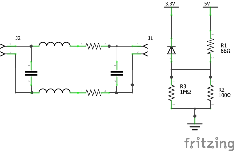
The “resistive divider” I assume is the same as a “voltage divider” ( a series of resisters to drop voltage)? Is the 100 ohm resister your suggesting from ground to D8 (the input pin) acting as a “pull down” resister. And the 68 ohm resister is the “resistive divider” to drop the 5V to approx 2.4V?
Have never worked with transistors … so I am going to have to do some work before I can ask intelligent questions, but I think I will start with the “model of a simple switch” where the “base” receives a low current which allows a larger current to flow from the collector to emitter.
So my assumption at this time is connect the low voltage from an output pin (using the “set high” command) to the base of the transistor, and allow the greater current (5v) to flow from the collector through to the emitter. From there to the + buzzer, and back to ground.
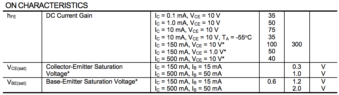
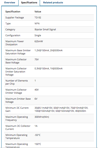
I am attaching a part of the data sheet from Jameco for the 2n2222 which you mentioned. I just need to figure out what all the information means. If I am reading this correctly the information I need to understand is in the “On Characteristics” section.
I am using a Piezo buzzer running at 3 - 15 VDC … drawing 10 mA at 12V. (Jameco part #2117430). 90 db is nice and loud, but the lower voltage will probably result in a lower sound volume.
I will try to deal with the “power supply” bypass when my head is a little clearer.
the voltage divider is 168 ohms over 5V so 29.7 and change ma flowing. Thus we see 2.9 V at the 100 ohm resistor and 2.01 V across the 68 ohm resistor with 5V (and of course 0V at both and no current when 5 V goes away). So the micro input sees between 0 and 3V and is happy. You are correct, the CPU in the MKR 1000 has lower output drive, I think 8ma minimum from the data sheet. That is more than enough for the 2n2222, the value of importance is hfe (or current gain) at 50ma collector current it is at least 70 which means it will sink 70 times the base current. So 5ma in to the base will mean the transistor could sink up to 350 ma and we only need 50ma so 5ma would be lots of drive and not strain the cpu pin. Now we need to calculate the base resistor value, the emitter base junction will take about .6v of the 3.3v input leaving us 2.7v across the resistor. So if we choose a 470 ohm resistor (rather than the 330 shown) we get around 5.7 ma of base current and everybody should be happy. The diode across the relay coil absorbs the inductive kick when the transistor switches. If you replace the relay with the buzzer (which isn’t inductive) you shouldn’t need the diode.
All good stuff … let me absorb these concepts, and I will reply after doing some breadboard mockups to get my understanding a little clearer.
One quick question - If I look at the voltage divider diagram on the left, I would think that 5V input going to the digital input pin would only see 68 ohms of resistance (before the branch) and not a total of 168. The 100 ohm resistor is “after the branch” … what am I not understanding. I can see that anything after the total of the two would see a voltage drop based on the combination of the two resistors.
I will do some mockups and think about it some more.
Yes, but I (and I expect most experienced folks) tend to forget that newcomers don’t have the other laws that apply hard wired in to their brains. In this case kirkoff’s law comes in to effect because this is a resistor network. We need a bit more complete (but still not anywhere near reality such as a spice model) drawing of this equivalent circuit. We still have the external voltage divider R1 / R2 but the cpu input pin is a bit more detailed, specifically its input resistance (which is probably really higher than a meg) and the substrate diode which is the real issue in over voltage on the input pin. This drawing contains a more accurate representation of both the voltage divider and the 20 feet of 26 wire to the sensors (which we will use later).
For why the voltage divider works the way it does, we need to add kirkoff’s law to ohm’s law. Essentially kirkoffs law says the sum of the currents flowing in to a node equals the sum of the currents flowing out of the node. For us that means resistors in series add their values (so the 100 ohm and 68 ohm resistor provide 168 ohms across 5V). The current flowing in the 1M gate resistance provides so little current that it can be ignored (if it was 100 ohms the the cpu input pin would see 50 ohms rather than 100 and the voltage would change in an undesirable way). Essentially the values (under normal conditions) of the components in the input pin for the cpu make have no effect on the voltage divider and the voltage at the input pin will be 3 volts. The problem with supplying more than 3.3 (actually more than 3.9 or so) volts to the input pin is the substrate diode that connects from the pin to the 3.3V supply in the chip. If we supply 5V to the input from a low resistance source (such as a 5V output driver that can source 40ma) the diode will conduct and attempt (and if it has enough current will succeed) to drag the 3.3V power supply and the chip to 5V. High current and damage to the 3.3V chip are likely to occur here. I know this from unfortunate experience because I tried to do some 3.3V level translation with a 74hc series chip (with the mistaken belief that it didn’t have the substrate diode, which in fact is only true for some members of the 74ahc family). Luckily I had disconnected the 3.3V device that I was driving before trying this so all I blew was the 74hc device and the driver pin on my arduino CPU chip as it dragged the 3.3V regulator up to about 4.5 volts through the 74hc chip.
A 74ahc chip in the same circuit works fine (and the document that stated 74hc did too has been removedfrom the site where I found it ). With that done, now on to your sensors 20 feet over 26 wire … To the left in the drawing you see an again simplified representation of what that wire looks like electrically. It has resistance (about .8 ohm for 20 feet of 26 according to an online calculator) and inductance and capacitance. The resistance might affect the voltages seen at the sensors, it is also small enough it may not matter. There are two considerations here: first as noted the sensors want somewhere close to 5V (or 3.3V) for power and may malfunction if the power drops below about 4.5 or 3V respectively. Bypass capacitors at the sensor end will help with this (as will the fact that the sensors don’t draw much current typically. If you can using two wires to supply 5V and ground to the sensor end of the cable and then with bypass capacitors on the sensor end of the 5V lines use a 3.3 V LDO regulator to provide the 3.3V to the sensors. The other related issue to be aware of is signal level noise immunity. A digital input typically accepts between 0v and .7V as being low and 2.4V of higher as a high (and voltages between .71 and 2.3 are undesirable for a variety of reasons, and should be transitioned through fast). The capacitance, inductance and resistance in the 20 feet of wire conspire to make this difficult. The effect of the three is to slow down the transition from a 1 to a 0 (and visa versa). If there is sufficient current flowing (which there likely isn’t in this case), the resistance can produce a voltage drop in the wire where 0V at the sensor shows up as .8V at the cpu end (the .8v being dropped by the .8 ohm resistance of the wire if there was 1 amp of current flowing). The effect this can produce is similar to what bypass capacitors help with on the power supply leads: it works 99% of the time but %1 fails because a 0 was read as a 1 due to voltage drop in the cable. It would be a good bet to try the sensors on the cable preferably in the place where it will be used to make sure it works acceptably. If not you would need to consider line driver options to get the data reliably from the sensors to the cpu (although I suspect this may work fine as is).
As it stands you won’t get plated through holes. Your pcb is set to single sided and it needs to be double sided to get the top copper hole to plate through to. If you have no objection to double sided boards, that would fix your jumper issue as well. If you change to a double sided board on both you will get the top side pads plated through holes and on the cpu module can route the jumper connections on the top layer getting rid of the jumpers (I have been assuming you wanted to keep the design single sided, which perhaps you do).
Sorry for the delay in responding to your comments … much appreciated. I have been doing my homework on “divider circuits”, KVL and my understanding of transistors and just general circuit design … Whew!!
I am attaching a test schematic with notes to see if I am on the right track. It is pretty simple, and only addresses the warning light and buzzer. I will work on the “bypass” capacitors next.
Thanks again for your input … hopefully I can someday pass it forward as well.
As your circuit stands there isn’t a ground return path for the emitter and no current limitation (which would be a disaster if there was a return path). While the I/O port is only allowed to source 7ma, it will try and source as much current as the circuit demands, thus we need R1 in the diagram to limit the current we will draw from the IO pin. When it is high it will be 3.3V, the base emitter junction will be about .7V (and if connected directly, draw way to much current and likely damage the cpu). The 470 ohm resistor sees 2.6V (3.3 - .7V for the base emitter junction) and thus limits the current to around 5.5 ma (a little less than the max of 7ma for safety). The transistor will sink around 60ma with that base current with the buzzer taking 25ma and the led taking about 20 for a total of about 45 ma which should work fine. If your wall wart is putting out 6V, it is either broken, or more likely unregulated (in which case it may put out up even more than 6V under light load). A regulated wall wart (which is what you want here) should always put out between 5.2V and 4.8V until its current limit is exceeded (at which time the voltage will drop to protect the wall wart).
It is becoming clearer I think. If you look at the notes I have on the schematic, perhaps you can critique my logic and see if I am understanding the process.
You will see that I am trying to not just copy your layout, but to clearly understand what the reasons are. I have changed it to reflect a parallel circuit with the LED and resistor on one branch and the buzzer on another. Hope that is not a problem.
This is my logic:
From your schematic, it seems that the only purpose of the D4 output pin is to “close the gate” of the transistor. Simply provide a path from IO pin to transistor base, and then to ground.
The LED and resistor need to be within one circuit (or branch) … and the buzzer can be on another branch … correct? That would mean that the total current for the circuit would be 20mA (LED) + 25mA (buzzer) … 45mA total. Looking at the spec sheet for the 2N2222 transistor, the “gain” is a factor of mA input and voltage. I see the gain as somewhere between 50 and 75.
Rather than try to supply the current and voltage from the IO pin D4, I want to create a path from VIN (or the 5VDC power) on the MKR1000 … through the “collector” to the “emitter” and then to ground. I chose the VIN because that is coming directly from the regulated power supply and would not be limited by the MKR1000 5VDC output. Correct?
Yes, the current from the base to the emitter junction is what is amplified to cause the collector current you want. Having the emitter on ground makes that easy to arrange and in general currents that get quoted are maximum limits that you are expected to not exceed rather than what will flow if you short the pin (that is usually much higher than the rated current and can damage the chip). So the 470 ohm resistor limits the base current to something the CPU is willing to provide. Going from the on semi data sheet for a 2n2222, the hfe of 50 is worst case at around -50 C at room temp and 50ma of collector current it is between around 70 to 100 (and I usually use 100 as a reasonable value) so with 5ma in to the base you should have plenty of drive. The data sheet is here:
and figure 3 is what I’m using for the hfe numbers.
Yes that is a good bet. The 5V output from the CPU is likely from a voltage regulator which will have a current limit, but supplying the current directly from the wall wart is a lot better bet as the wall wart is likely to be more forgiving of error than the CPU and the led and buzzer don’t care where they get the power as long as they do . If you find the buzzer is too loud you can put a resistor in series with it to reduce the output. It may be a good bet to put one on the board and jumper it with a piece of wire. That way if you find you need a resistor to lower the volume you have a spot on the board where it can go. Your second 5V supply needs a connection to ground, but other than that all looks good. It looks like you have some extra rats nest lines in schematic which usually means either data base corruption or bad connections on breadboard (which reflects in to both schematic and pcb). You likely need to check that the connections in breadboard match those in schematic. We used to think this wasn’t curable without starting a new sketch, but I found that if you move everything off the breadboard and delete all the wires (and some of them were hard to find) that the data base will recover. In any case other than the bogus rats nest lines, the circuit looks fine.
 , they all need the power supply bypass capacitors (a .1 or higher ceramic and a 10 uf or so tantalum) to insure the 5V remains 5v after all that wire. The temp sensor is likely to have noise problems with an analog signal in that much wire. You would be better off using something like a DS18B20 one wire temp module so that the temperature comes across the wire as a digital signal rather than analog. An example of using one is here: