To generate the Gcode in bCNC app, to be applied on a CNC router (Arduino with GRBL), the SVG image generated by Fritzing (_xxx__etch_copper_bottom_mirror.svg) would have to be reversed: where is black should be white and vice versa.
Someone might inform how can I solve this problem?
While I’m not sure I even understand the problem correctly, if you want to change the colors of an SVG image you can either use a package like Inkscape and it’s XML editor or use a text editor on the svg file. As an example this is part of a pcb svg file edited with vi under cygwin (although notepad should also do):
circle cx="3.6" r="2.88" fill="none" stroke="#FFFFFF" stroke-width="0.72" cy="68.4"
for your task the stroke="#FFFFFF" and specifically the #FFFFFF (which is white) is of interest. To
change that to black change it to #000000 (and visa versa to go from black to white).
The copper pads are a golden color (the above being the silkscreen layer):
circle cx=“43.2” r=“2.052” fill=“none” gorn=“0.1.0.0” stroke="#F7BD13" id=“connector14pad” stroke-width=“1.224” cy=“3.6”/>
their color being #F7BD13 which you could change to black or white if you wanted.
You answered my question, I thank you for your attention.
Inkscape can be a tool to change the vector graphic color, but can also be used “Developper tools” from Google Chrome to edit the color of each component vector of the image SVG … but change the vector color does not solve the problem.
I think that I did not properly formulated this question considering that this is a vector image and I might not get me adequately express in English; I apologize.
I try to better explain the problem …
The Fritzing can generate a set of vectorial SVG graphics for the production of PCBs, among which is especially important _xxx__etch_copper_bottom_mirror.svg graphic to “print” the botton layer.
The graph of this SVG layer containing the vectors in the proper format for PCBs but not appropriate to generate the gcode used by a CNC, that is, this graph would have to have the “inverted” vectors in the image: the vectors should be present where the image is white.
The CNC “cuts” where there is a vector in the image.
In _xxx__etch_copper_bottom_mirror.svg graphic, cut where it is black, where we do not want to cut. In this case we want to cut which is white but white is just the image background, is not a vector.
The question is how to generate “negative” vector of _xxx__etch_copper_bottom_mirror.svg image, ie, vectors forming where the image content is white.
(Note: although I do not believe that the CNC is the best way to produce a PCB, I assembled a CNC to study and would like to try this process.)
Just swapping the colors did seem a bit to easy to me I don’t know of a way to do this (although I’m also new to Fritzing and someone else may have a suggestion). You may be best off using google to search for a program to do this from the cnc folks, I’d expect they face this problem more often than the Fritzing folks. Good luck!
I know there is software for routing PCBs as I had done some research on it awhile back. All of my links on this subject were on a old computer which had died… If you do a goo search and checkout some youtube it may lead you in the right direction. I did a quick search… here are a couple of links…
There seems to be a preference for the use of the Eagle (to draw the schematic and PCB) and its PCBGCode plugin (to generate Gcode). Among some of the PCB design software that I rated, I realized that the Eagle is the most difficult to use, the less intuitive. Unfortunately.
I like Fritzing but it is still a very early stage.
I hope Fritzing to improve the supply of other export formats, as well as resolve compatibility issues of the formats that have (I have tried exporting my PCB Fritzing to the Eagle and I did not succeed).
The bCNC is the application that connects to the Arduino GRBL. I do not know another application to do that, so I have to work with bCNC if I want to continue using the Arduino. I want to continue using the Arduino for various reasons even though this is not the best CNC platform.
Among the formats that can be opened by bCNC I can name the SVG and Gcode but not the Gerber.
I initially tried using the SVG generated by Fritzing but there is some incompatibility between the SVG exported by Fritzing and SVG imported by bCNC because no Fritzing SVG graphic can be imported into bCNC. This is a problem.
Another problem with the SVG graphic generated by Fritzing is that they can not be handled by Inkscape just as an SVG graphic generated by Inkscape can be handled by Inkscape itself. Try using the tools Union, Difference, Intersection, Exclusion, Division (in the Path tab) in SVGs generated by Inkscape and SVGs generated by Fritzing. If there was not a problem I could work the SVG graphic generated by Fritzing ( “xxx__etchcopper_bottom_mirror.svg”) for the negativet it with the Exclusion tool.
So the solution would be to export a Gerber generated by Fritzing for Eagle generate Gcode to be used by bCNC but Gerber that Fritzing generates is not fully compatible with the Eagle and the result of the migration is unsatisfactory.
In my opinion the best solution would be obtained if the Fritzing generate SVG fully compatible with Inkscape’s tools but this is not in my power.
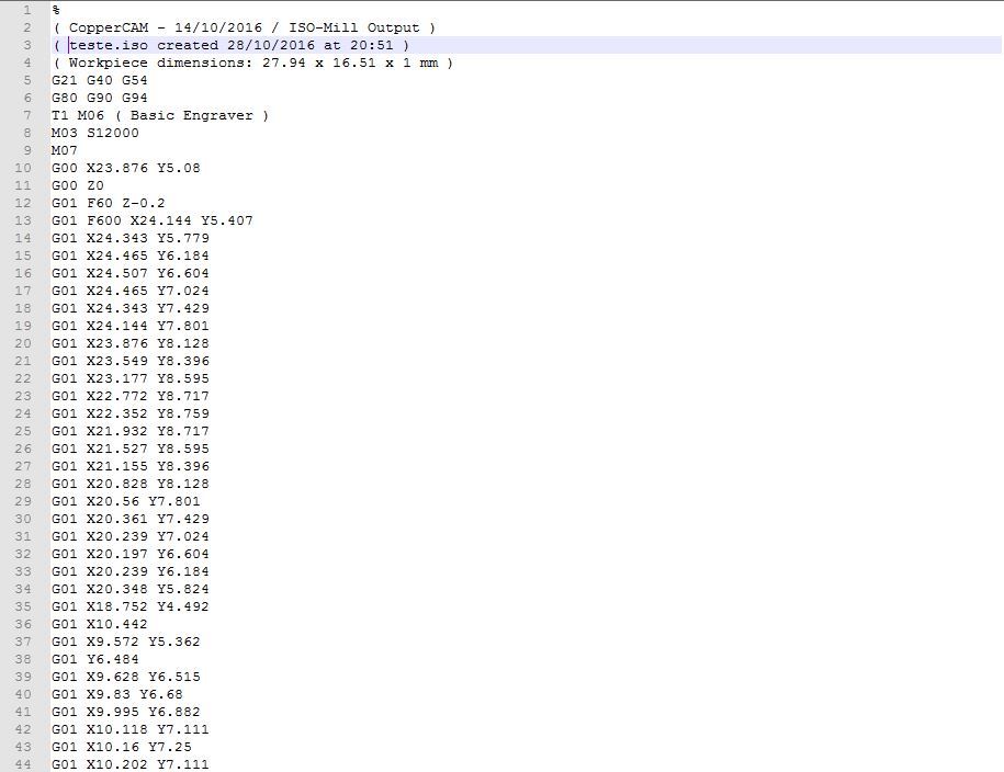
This is a board that I created on Fritzing and had it fabricated by OSH Park earlier this month. The gerber I used in CopperCam is the same one I sent to OSH Park. Below is a sample of the g-code I generated from this gerber. This board has 8 mil trace and a few 0.3 mm laser drill holes, and is not likely it could ever be milled on a cnc machine. I didn’t set anything up on CopperCam, this was generated out of the box.
I had thought about building another cnc machine and trying this out… sounds like a good winter project…
Yes, a board can be cnc milled using Fritzing gerbers… You may need to design the board a little different than you would for a fab shop.
I built my own CNC specifically to mill my own prototype boards.
I use an arduino with GRBL.
Export your PCB as a PRODUCTION GERBER
This generates everything you need,
Download FlatCAM ( only windows) it is free and wonderful.
Open the GERBER file for COPPER BOTTOM
Follow the rest of the FlatCam steps.
a) I use a .1 mm 10% CNC bit; works like a charm.
b) You must auto level your board. Don’t skimp on this ste p. Get as many data points as you can get within reason.
IF you are doing .1 mm on center type of works you need more data points than doing 2 mm spacing work.
c) DO NOT USE THE CNC BIT FOR AUTO LEVELING. Use a hard steel or brass rod with a dull point.
I will be putting a video as soon as I get a chance. Happy Milling…
There is a problem with my Flatcam that is not able to open GERBER (xxx__copperBottom.gbl) or import SVG graphics.
I have no experience with Python and I do not find easily the solution to this problem.
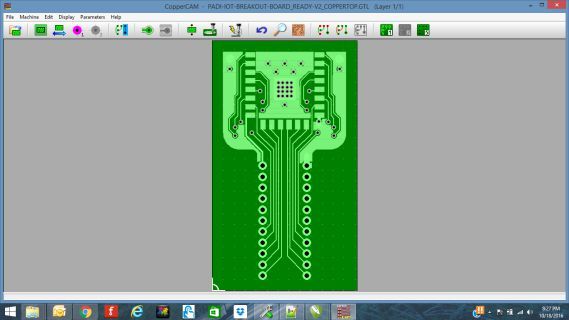
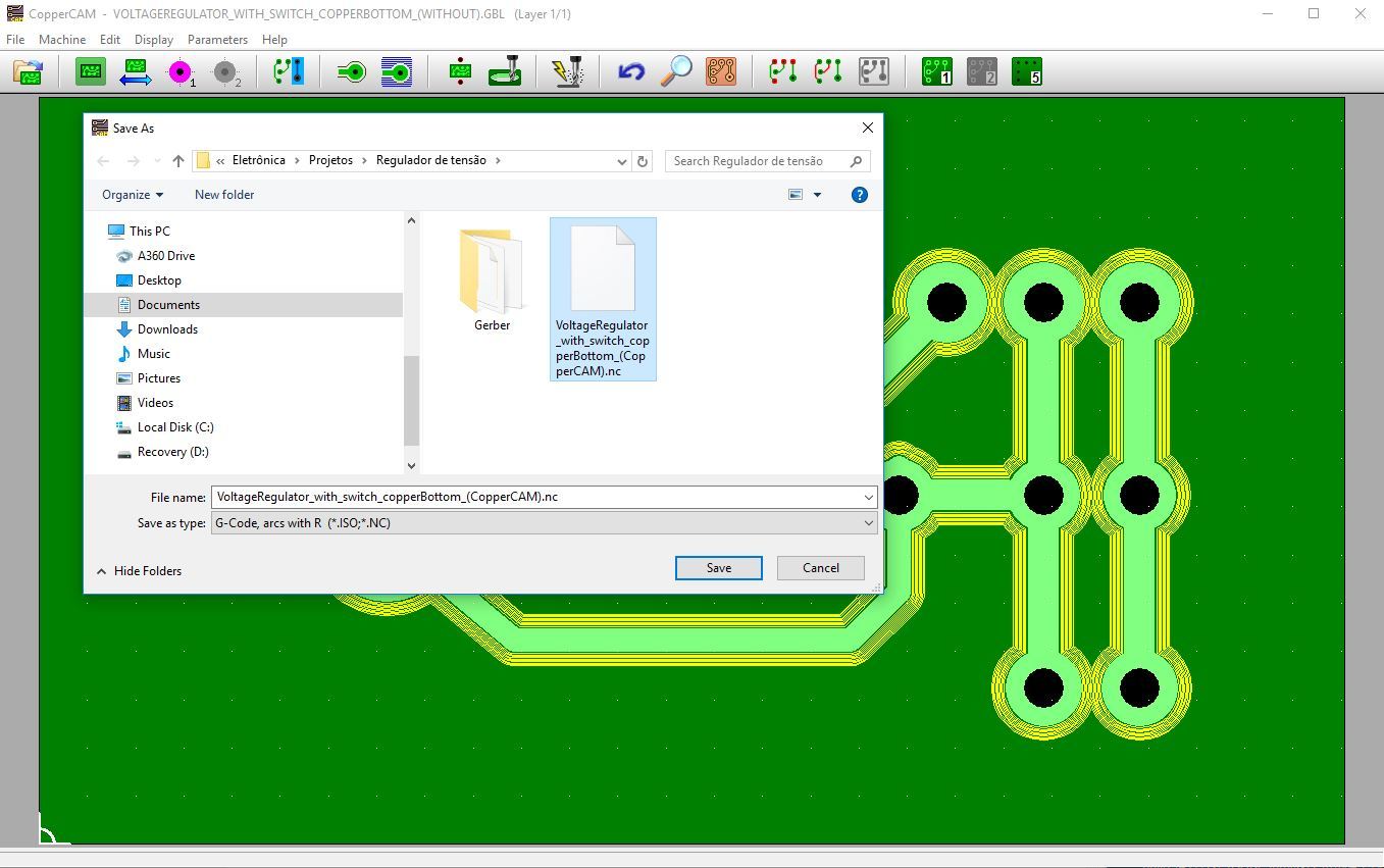
I installed CopperCAM and tried to work the image VoltageRegulator_with_switch_copperBottom.gbl but I’m still trying to understand how this tool can help me.
Therefore, I do not understand how You could generate Gcode from Gerber Fritzing (version 0.9.3) but I suppose You could have had a lot of work.
In my opinion, the biggest problem is the quality of Gerber generated by Fritzing, with regions divided into blocks that should not be divided to generate a Gcode. This can be seen in GerberFritzing.jpg and already mentioned in another post here, in the Fritzing forum.
Can you explain in a little more detail how you worked Gerber generated by Fritzing in CopperCAM tool?
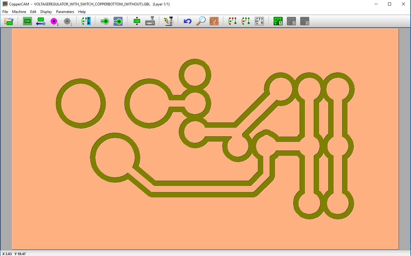
PCBs to be routed are designed different than you would for chemical processing. For one, if you want copper fill on a chemical processed board, you need to add copper fill in your PCB drawing so it will be included in the negative and the copper will not be dissolved away in the chemical process. On a CNC router, you don’t need to include copper fill in your PCB drawing. All you want to do is rout out the traces. The copper fill (remaining copper) will remain on the board whether you have copper fill in the PCB drawing or not.
I understood.
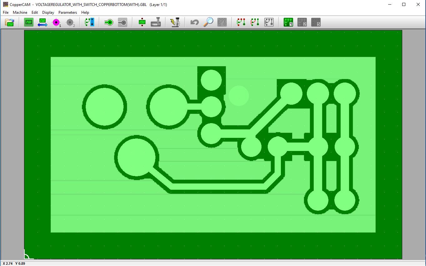
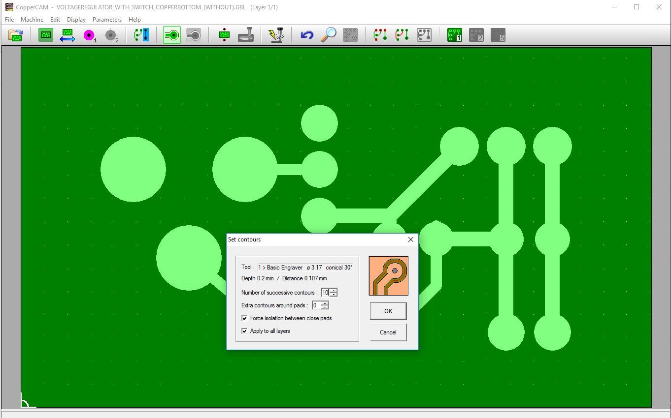
After reading a CopperCAM manual written in Portuguese (Brazil), downloaded from the Internet (CopperCAM website has no manual), I’m thinking that for a Gerber generated by Fritzing work in CopperCAM the PCB of this Gerber can not contain copper fill (Fritzing -> Routing -> Ground Fill -> Copper Fill).
We must let the Copper Fill (or Ground Fill) is created in CopperCAM.
Am I right?
Gerber with copper fill in CopperCAM (this Gerber should not be used in CopperCAM)…
That is awesome… now we know Fritzing Gerber files can be routed with CopperCam and how it is done… This should be a good link for anyone who is interested in making PCBs with a CNC router…
I expect you would do better asking in the CopperCAM forums than here. There is more of a chance that someone using CopperCAM would know about Arduino compatability and how it can be achieved (if it can be achieved) than anyone here.
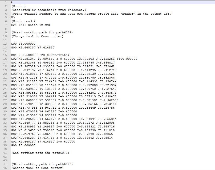
Yes, you would need to setup a Post-processor for the GRBL (Arduino); In CopperCam, in the menu, click on Parameters / Data Output Format, and then click on the Format: combo-box, click on Post-processor “ISO standard” bottom of the list. A dialog box will open for you to write your own Post-processor. The g-code is not that far off… You have six decimal places, you only need three, the z-axes does not need to be printed on every line, and the lines with I### and J### are curve coordinate…
You probably need to check out GRBL (Arduino) for the Post-processor format…
So I guess now I’ll have to learn some G-Code and I found a good place for it on the website CNC Coockbook.
Unfortunately there seems not to be a forum dedicated to GRBL, then issues related to this are scattered in several forums, chosen according to the initial purpose of the discussion.
I am very grateful that you have shared your knowledge, that you have not left direct this issue to the void. I believe you have also collaborated with the evolution of Fritzing, this excellent tool.
It is not as difficult as it looks… Depending on how your router is set up; like, is your spindle turned on by the controller or manually… if you turn it on by hand then you don’t need the M codes to turn it on and off. Some controllers won’t do circles, they need to be generated in two half circles… Try a simple generated code with just a couple of lines and curves to see what is does.
You can also edit the Post-processor by hand; go to C:/CopperCam/ISO.ppf and open it up with a text editor. This is the ISO default Post-processor. You don’t need to create/edit the Post-processor within the dialog box, you can just do it by hand in a text editor and save it under a new name. That is the way I always had to do it. You can open up anyone of the .ppf files and look at the difference between them, or edit and save under a different name. The Post-processor format in for all machines, you just need what works on your router…
 I don’t know of a way to do this (although I’m also new to Fritzing and someone else may have a suggestion). You may be best off using google to search for a program to do this from the cnc folks, I’d expect they face this problem more often than the Fritzing folks. Good luck!