I noticed there was another Fritzing repository called “Eagle2Fritzing” which is supposed to turn any .brd or .lib file (from Eagle) into Fritzing parts (svg files). After looking at it and noticing there was a updated version (and tutorial) from Adafruit, I went into testing it on my Windows OS. Unfortunatelly, the current tutorial isn’t updated and therefore, I had to do some try-and-fail procedures in order to make it work.
How to make it work on Windows?
1. Install Qt creator and check the 5.6 version along with MinGW 4.9.2. 2. Clone the github repository Adafruit Eagle2Fritzing.
Place it in same folder along with Fritzing-parts and Fritzing-app. 3. Open the folder via Qt 5.6 for Desktop using cd path/to/eagle2fritzing/brd2svg. 4. Run qmake brd2svg.pro and then mingw32-make. 5. Now open the run.sh file using a code editor like Notepad++ or Atom and edit the following variables:
EXEC: Location of EAGLE executable, I recommend replacing the whitespace of default eagle path (EAGLE X.X.X/eagle.exe) with an underscore (EAGLE_X.X.X/eagle.exe) so you don’t have to deal with whitespace in shell script (which never worked for me).
WORKPATH: Default brd2svg working path (override by passing argument to this script).
TESTPATH: Converted parts will be copied here for testing on Fritzing.
Ummm I will give it a try with another part as long as I get the eagle files (.brd or .lbr).
Of course I don’t expect it to be perfect but save me tons of time to make parts like these, so I will do the correct fixes in order to import it into Fritzing.
On 2nd thought can you upload one that has a lot of pins because we usually see millions of duplicate nodes in old parts that we presume is the Eagle2FZ, and if has a lot of pins it would show up more pronounced.
If someone posts a part (best) or even just the breadboard svg above as an svg I can run it through the script and see what it says (and manually look at it for issues). That said, if it makes parts easier to make for you I’d say use it. I remember a comment from one of our other part makers a year or so ago that he had looked at the python code for this with a view to improving it but that it was to complex (and I assume undocumented) to make any progress. A fair number of the parts in core have been created with one version or another of this script so I don’t know that there will be more complaints than usual but I also don’t know how many of the parts have been manually cleaned up after such conversions either by el-j or the author of the part .
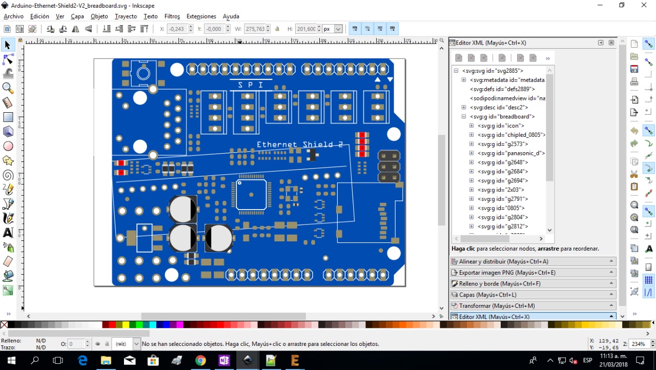
That does look pretty odd! It looks like they had to angle it (very probably as a retrofit long after the original board was made) to be able to fit the POE transformer somewhere where it would physically fit and not short something else while still being low enough that you could stack a shield on top of it. I’d guess looking odd took last place to working (a sentiment I can agree with ).
I somewhat suspect (but without data to back that up) that we will find the dup pins are more an artifact of copy/paste in Inkscape (I know I have done so before and had to edit the resulting connector values to maintain sequence) than the eagle script, but I may be wrong. There is also code in the source (I don’t at this point know if it is active or not) that will do kicad and I think eagle file conversion to fritzing. Its more than possible this is work in progress that isn’t actually running yet, but it seems to be there in some form. That said test data would be interesting.
I was mainly thinking of something like a big IC part, like maybe a Atmega 2560 chip. The problem I keep seeing on most parts is that there will be pads on pads on id pins on more id pins etc.
So you’re saying that the Eagle2FZ makes a svg, and then you load that into your part, and when you export it it has nodes on nodes ad infinitum.
Thanks, I’ll have a look and see (I’m a bit slow right now because I had an eye operation last Monday) and my vision is a bit impacted as I recover.
As I said I’ve not used or looked at the eagle script (I only actually downloaded eagle to get a footprint of something a few months ago) so I’m repeating (from memory as well ) what I remember hearing from others many months ago. I think the adafruit version is considered the most up to date. I don’t know if that is the version on the Fritzing repo or if there is a newer one on adafruit’s repo somewhere. Looking at file timestamps may be a way to tell, as may be searching for eagle or eagle to fritzing here in the forums.
No not exactly. My impression (without having used it) is that eagle to fritzing generates a full fzpz file from the eagle input (which may or may not have dup connectors). When I’m making a new part because I’m lousy at breadboard, I tend to find a part that will do what I want that someone more skilled has made and use copy/paste in Inkscape to copy the part of the svg I want in to my new part. When doing that if the part I copied has connectors, they will get copied in with their current connector id (typically with a -number such as -3) on the end. They are typically the same as the existing connectors in the svg (assuming I started from something with connectors). I think that is a more likely source of such issues that the script (although I could of course be wrong). An example would be a good thing so we know where the issue is coming from.
Yeah, it can do it as long as you have a proper board file (*.brd) with all the required layer stuff. Due to my lack of skill on this field, I couldn’t find a single component file as the one you posted neither could do a proper one from scratch because there are required layers to make it work which I don’t know.
Gee, that Eagle was so hard just to put a 74ALS634JD on a PCB I gave up.
From now on if I see a Eagle2FZ part in FZ I’m going to throw it in the bin because I don’t need to waste time deleting nodes on nodes on nodes when drawing it from scratch is quicker.
I told you it was hard but I’m sure this updated code isn’t stacking nodes. Anyway, as I said before, I will use the result and clean up so other users doesn’t have to deal with weird stuff.
If the issue is deeply nested (and pointless) groups, yes I think that is the Fritzing parts exporter. The converted Fritzing schematic svg however isn’t all that good. There seem to be only two pins where the eagle original has many more that don’t show in the Fritzing version.
I don’t know what happened with the SCH - I might not know Eagle well enough - but I remember trying to mod parts and there was pads on pads with connector ids on connector ids, like everything was doubled or more. Maybe that was FZ 9.2, and when you exported it it added all that stuff like it does with groups now.
The code provided by adafruit (Eagle2Fritzing) only requires .brd file to work, not .sch ones. Probably Old_grey didn’t placed / named properly those pin connectors but who knows? This code work pretty good with professional board files provided by manufacturers like Arduino, Adafruit, etc. There must be a hidden / attached property to make the code recognize and place the proper pin label / connectors at schematic view.

/i/27562/products/2015-11-11T18%3A38%3A12.594Z-Atmel-ATMEGA2560-16AU-image.jpg)