I have a test shield for the Uno that has a built-in SD card. My project has exceeded the capacity of an Uno and was looking to use a Mega 2560. Plugged in my card only to find the SPI pins on the mega have moved to the ICSP header. Most of my shields use the SPI pins on the Uno, 11, 12, 13 I believe they are…
It seems one can make an adapter shield with jumpers of some sort that can ‘map’ the functionality of the SPI pins between 11, 12, 13 to the ICSP header, maybe another setting to make the pins pass-thru to other shield, etc.
Before going down this path, surely someone has done this already or there is some obvious problem that I am missing.
Let’s say I have to make one or decide to make one of my own for whatever reason… The ICSP header I would want to use would be a long pinned female type connector pass-thru hole … ? I did not find this part in the large list of parts. Am I missing it?
Lastly, if I add my own SD card, is there a chip of some sort needed? Or do the pins go directly to the ICSP pins? My existing shield looks like it has a real small ship with no markings that I can see.
Since this is the only part I know anything about I’ll answer this. The SD cards are all 3.3V as far as I know so assuming your Mega is running at 5V the chip is likely a 74ahc125 (I made a Friting part for this that is available in parts submit). The 74ahc125 with VCC at 3.3V will tolerate 5V from the Mega on its input pins (unlike the SD card) and output the signal at 3.3V to the SD card. Putting 5V in to the SD card may damage the card.
Thanks Peter. I am using your part. Can you kindly tell me what pins go to what pins? I’ve never used a buffer before. Nothing on Google came up when looking for SD card and 74ahc125.
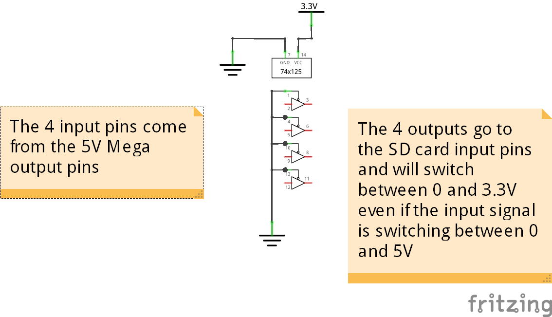
Here is a schematic (note that the part needs to be a 74ahc125, none of the others such as the 74hc125 will do level translation which is what you need.)
The part has tristate outputs, so the enables are all tied low so the output is always enabled. What you are doing here is 5V to 3.3V level translation, but there isn’t all that much information about it available on the net for some reason. I found the 74ahc (only some parts in the series though) explaination in a TI application note on level translation. There are also other level translator chips available but this one is cheap and easy for this application.
I often use sdCard adapters on Arduino (UNO, Nano, and Atmel chips on a PCB or Breadboard). I just finished an indoor lap counter (to count laps I jog in the house 14 laps = 1/4 Mile… LOL)
A summary of what I’ve learned: Using something not specific to a board/device has worked the best for me for these reasons:
• Can use different pins
• Vin = 4.5 to 5.5
• They have their own 3.3 Voltage regulator
• They work with the varioius Arduino sdCard libraries
• 5 units for about $8
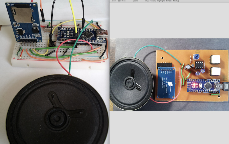
Well my PCB prototype is complete! If the SD card doesn’t work I’ll swap it out for the pre-done ones that are mentioned here. It would probably make my PCB single sided too. Hmmm…
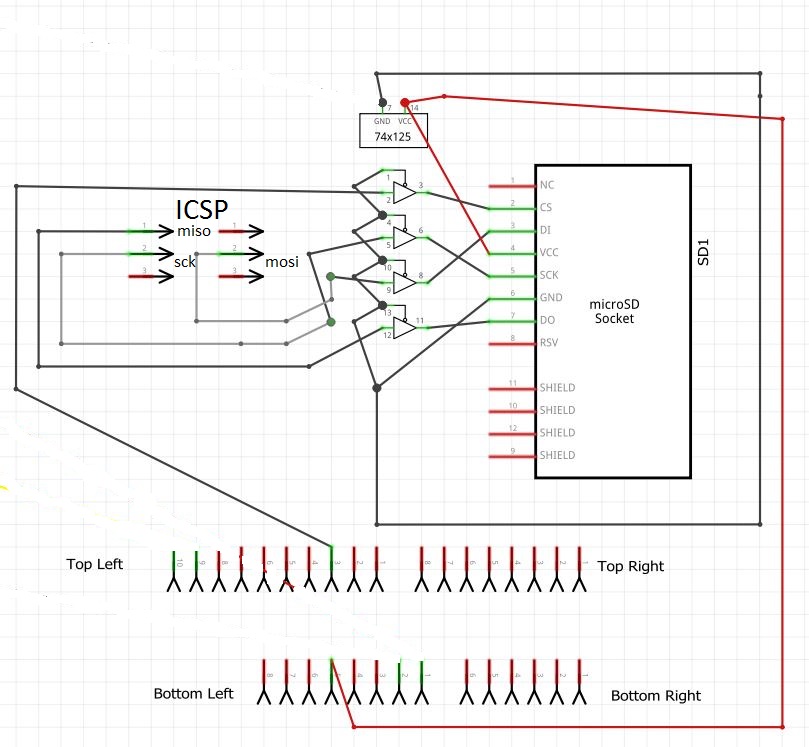
The pins are the bottom represent the Arduino UNO pinouts… Top left is CS, Pin 10. Bottom is 3.3 V. Just noticed I am missing the ground symbol but everything is grounded.
UPDATE: I have separated the VCC input on the chip (now goes to +5) and sd card reader (stays at 3,3).
Before, both were being powered from the 3.3.
Sorry for the late reply (I’ve been offline for 2 months with a broken ankle).
This is incorrect. The 74ahc125 (and it needs to be an 74ahc125 none of the others will work) should have VCC connected to 3.3V. When CS (pin2 on the 125) is at 5V the output to the sd card from pin3 (as an example) should be 3.3V. Checking this with a multimeter is a good bet, if the output to the SD card isn’t 3.3V something is wrong and the SD card may get damaged.
Can you take a look at the link I posted above and confirm this is the correct part? If it is, there must be something that went wrong with my surface mount soldering.
The different pin numbers on the socket confused me. miso (DO on the socket) shouldn’t be level translated and is in the wrong direction. DO is the data back to the micro and will make this not work. VCC needs to be 3.3V and the IC a 74ahc125 and pin 12 of the 74ahc125 needs to be grounded (as it is unused and cmos doesn’t like floating input pins). This site has a wiring diagram for an SD interface. Here the 74ahc125 is the level shifter in the schematic.
hello, here to share:
I power my arduino nano directly with 5V or lithium battery power, as well as the SD card.
most they works fine, sometimes (<2%) the card went hot and needs restart.
if you have trouble with level shifter , skip it and try?
note that some SD adapter has pull down resistor over level shifter,
if you don’t insert a SD and the pins were floating, pull-downs were still likely to interfere your SPI port, in case you use other SPI device.
You are correct! All I had to do was connect MSIO directly to the arduino and it works!
Sorry for the delay. It took me awhile to get the time and then even longer to breadboard it, then figure out my PCB.
Thanks!!