DC-DC Converter with XL4016

Hello!

I just made another piece that couldn’t find on fritzing for my electronic project, a DC-DC converter using the XL4016. You can google it and will find many different “manufacturers” with slighty variations between them but the same appearance. You can check the Datasheet XL4016 and the whole Spanish Schematic DC-DC Converter with XL4016.

Following the tutorial, here is the fritzing file :smiley:
DC_DC_Converter_XL4016.fzbz (115.3 KB)

And a little preview:

DC_DC_converter_breadboard

Leave your comment if you liked it :laughing:

3 Likes

My initial comment is there is something wrong with your xl4016 file in the bin (I haven’t yet tried the other 2) that hangs fritzing due to a bug I’m in the process of fixing. If you load it you will likely need to delete the frtizing user files (after killing fritzing) to recover. I’ll have a look at whats wrong with the files and post a fixed up version. As well as I said in another post, its better to post the fzpz file of a single part rather than the entire bin.

Peter

I have followed your suggestion and did again the export steps. I exported it as “xl4016” and then unzipped the generated .fzbz file.

This is what I got:

File list

Now shall I rename each file as .fzbz and upload here?

I was just editing my first reply, here is a corrected version of your part (not exactly correct yet but much better) and how I got there.

First I unzipped your fzb file to get

DC_DC_Converter_XL4016.fzb
‘part.MPU-6050 GY-521_27d4eab32ad654bb2011bfb7d4e898dd_3.fzp’
‘part.Sensor Shield v5_bfaee848f06338d8b00dadc40aa01172_15.fzp’
part.xl4016_c78f89428dcf787d84bc8d8066ed2354_10.fzp
‘svg.breadboard.MPU-6050 GY-521_5bd41e1b055f687022fb2f2e39366183_2_breadboard.svg’
‘svg.breadboard.Sensor Shield v5_5de0a662573cea8393973ba9d5686ea2_1_breadboard.svg’
svg.breadboard.xl4016_c78f89428dcf787d84bc8d8066ed2354_10_breadboard.svg
‘svg.icon.MPU-6050 GY-521_5bd41e1b055f687022fb2f2e39366183_2_icon.svg’
‘svg.icon.Sensor Shield v5_5de0a662573cea8393973ba9d5686ea2_1_icon.svg’
svg.icon.xl4016_c78f89428dcf787d84bc8d8066ed2354_10_icon.svg
‘svg.pcb.MPU-6050 GY-521_5bd41e1b055f687022fb2f2e39366183_2_pcb.svg’
‘svg.pcb.Sensor Shield v5_5de0a662573cea8393973ba9d5686ea2_1_pcb.svg’
svg.pcb.xl4016_c78f89428dcf787d84bc8d8066ed2354_10_pcb.svg
‘svg.schematic.MPU-6050 GY-521_5bd41e1b055f687022fb2f2e39366183_2_schematic.svg’
‘svg.schematic.Sensor Shield v5_5de0a662573cea8393973ba9d5686ea2_1_schematic.svg’
svg.schematic.xl4016_c78f89428dcf787d84bc8d8066ed2354_10_schematic.svg

then I edited the

part.xl4016_c78f89428dcf787d84bc8d8066ed2354_10.fzp

file which has incorrect values for the svg file names (which is why Fritzing hangs, because it can’t find the svgs).

Problems:

fzp filenames are incorrect, the referenced files don’t exist.

  <layers image="icon/xl4016_e051a9ea7b14f7f51eaa32f20e0976f6_2_icon.svg">

to

  <layers image="icon/xl4016_c78f89428dcf787d84bc8d8066ed2354_10_icon.svg">

then

  <layers image="breadboard/xl4016_e051a9ea7b14f7f51eaa32f20e0976f6_2_breadboard.svg">

to

  <layers image="breadboard/xl4016_c78f89428dcf787d84bc8d8066ed2354_10_breadboard.svg">

then

  <layers image="schematic/xl4016_e051a9ea7b14f7f51eaa32f20e0976f6_2_schematic.svg">

to

  <layers image="schematic/xl4016_c78f89428dcf787d84bc8d8066ed2354_10_schematic.svg">

then

  <layers image="pcb/xl4016_e051a9ea7b14f7f51eaa32f20e0976f6_2_pcb.svg">

to

  <layers image="pcb/xl4016_c78f89428dcf787d84bc8d8066ed2354_10_pcb.svg">

then change the 4

<connector name="IN-" id="connector1" type="female">

to

<connector name="IN-" id="connector1" type="male">

With that corrected, make a part by zipping

part.xl4016_c78f89428dcf787d84bc8d8066ed2354_10.fzp

svg.breadboard.xl4016_c78f89428dcf787d84bc8d8066ed2354_10_breadboard.svg

svg.icon.xl4016_c78f89428dcf787d84bc8d8066ed2354_10_icon.svg

svg.pcb.xl4016_c78f89428dcf787d84bc8d8066ed2354_10_pcb.svg

svg.schematic.xl4016_c78f89428dcf787d84bc8d8066ed2354_10_schematic.svg

in to

DC_DC_Converter_XL4016.fzpz

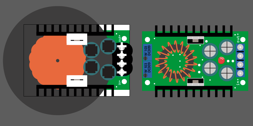
to make a loadable part file (still has problems but should load now). Indeed the new file now loads. This is a sketch that includes the corrected part with some test connections to check the part:

xl4016Sketch.fzz (14.5 KB)

If you download this and load it in to Fritzing you will get a sketch that contains the new part in the temp bin. If you right click on the xl4016 part in the temp bin and select “export part” it will export the new part as an fzpz file. Over all this is an excellent first part, most things are fine. However in schematic view you will see the rats nest lines are connecting to the center of the pin rather than the end as they should be . That is caused by the terminalId being either missing (in which case it will default to the middle of the pin) or in the wrong place (I think it is in the wrong place in this case as it doesn’t seem to be missing. When I exported the gerber from PCB view, the size of the holes on you board are .028in and should be .038in to connect to .1 in header pins. I’ll now make another part that corrects all the things the part script finds wrong and post a correct part so you can see what changes I have made.

Peter

1 Like

Woah! That was a fast fix. Thanks for pointing out the problem, I am newbie exporting even following the export tutorial wasn’t enough to do it correctly.

Now about the “pin” connection, it is supposed to be a “Screw Terminal Wiring Connector” (I think it is the name of the blue thing), that shouldn’t be soldered right into the PCB but for aesthetic reason, I placed the holes to help with PCB design. Not sure if you get the idea. :blush:

I will take into account your tips (you should do a tutorial?) when finishing the other part I am doing (Arduino Mega Shield 2.0) and check if everything is ok.

Once you get through the parts creation learning curve (which took me around a year) making parts becomes reasonably easy and fast.

Here is how I would make this part. The changes are

Made a new part (so both can be loaded in to Fritzing at the same time) with parts editor.

rescale the parts to the standard (optional, it will work fine without doing this, but it is desirable to have all parts at one scale).

breadboard

ungroup everything

rescale

move the connectors to be on .1 in grid (doesn’t match real life exactly probably but keeps the wires straight). Select all and group name the group breadboard. Without the breadboard group exporting the part as a svg doesn’t work.

Schematic

ungroup everything

rescale

reduce the size of the item to be on .2 inch centers (.1 in centers is the usual spacing for most parts though)
add 4 .01in rectangles as the terminalId as they were indeed missing and place them on the end of the pins (parts editor can do this as well). Select all group and name the group schematic to set the correct layerId.

pcb ungroup everything

rescale

group the connectors in to copper1/copper0 group

group silkscreen in to group silkscreen (the original was silkscreen_2 and thus didn’t show up in the gerbers).

fzp file:

removed the terminalId from the breadboard definitions (as they aren’t in the svg) not really necessary but neater.

Ran the part file through the parts check script to remove font-size px values and check for no errors Then zip them all to create this fzpz file.

DC_DC_XL4016_fixed.fzpz (13.7 KB)

which you should be able to load in to the same sketch as the one I posted earlier to see what changed (not that much :slight_smile: ).

I did although it probably needs updating with some of the things I have learned since:

I’m assuming Old_Grey’s videos are the tutorials you are currently using (which may be more useful than mine as well :slight_smile: ), if not they are available here:

Peter

2 Likes

Once you get through the parts creation learning curve (which took me around a year) making parts becomes reasonably easy and fast.

That’s a lot of time and experience for this, which is great as I saw the fixed model (pretty good indeed). I followed this tutorial and looks like I found another one made by SparkFun, which looks way better. Thanks for sharing the Tutorial Series, I would take a look at it as soon as I can.

Here is how I would make this part.

Wait, I didn’t understood the rescale part since I didn’t found a standard about parts sizing.
The connector was a good tip, I didn’t noticed it. The rest of thing probably are explained on the video, right?

Being a newbie is harder but glad to see your tips (and making effort for fixing this).

I have some questions:
When downloading custom parts, should I save them inside Documents/Fritzing/bin folder or just load them from my download folder and let the program handle it?

Also, there is a guide to add the proper description / labels for this new part? Because I used the default IC and slighty changed some stuff to make it fit (like as etiquette, category, etc).

For last, shall we upload it on github fritzing parts at core or different folder?

We seriously need a updated guide.

Cheers!

These two tutorials look to be for a previous Fritzing version. The new parts editor is both quite different (although the underlying parts are much the same) and not finished. The two tutorial sets I mentioned are for version 0.9.3b (the current release).

The part you started from was scaled at .75 the parts standard available here:

specifies a scale where 1px = 1 thou (which works out to a scale of 10.41667 in Inkscape. I wouldn’t worry to much about this, I automatically do it on any part I fix up so the scale is corrected if someone clones the part. A scale of .75 will work just fine it just isn’t preferable.

True, it all has a fair learning curve, but at the same time it is the only package I am aware of that has breadboard view which makes documenting a project build out of modules from Ebay possible. That alone is worth it to me to improve fritzing (and its fun :slight_smile: ).

I tend to keep a copy of any parts I download or make in a directory separate from the Fritzing one (although they are usually also in there). If you hit a bug as with your original post Fritzing will hang and corrupt the user database. That means you need to delete it and potentially restore all the parts (or keep a backup of the directory) to avoid that. I have a fix for this particular problem but it isn’t fully tested yet.

Unfortunatly no not that I’m aware of. Most of the information I have has been passed down from other folks in this forum. You are correct we need better documentation for almost everything, but we have no one (so far) with the knowledge and time to write any.

That at least is documented (although I’ve so far only done this a time or two, mostly I have been posting here in the forums) other than how to replace a part with a new version and obsolete the old one which is listed as TBD (To Be Done) …

Peter

The part you started from was scaled at .75 the parts standard available here:

Didn’t found the standard file on that wiki, where I should look into?

Also gonna share it on github if everything is ok :smiley: Even though you slightly moved the “+” symbol on the screw blue connector. Could I try to fix it or let it go as it is?

I tend to keep a copy of any parts I download or make in a directory separate from the Fritzing one (although they are usually also in there). If you hit a bug as with your original post Fritzing will hang and corrupt the user database. That means you need to delete it and potentially restore all the parts (or keep a backup of the directory) to avoid that. I have a fix for this particular problem but it isn’t fully tested yet.

Makes sense, although if It is bugged, I would just need to delete it from my parts only, right? When I did the first export, the program zipped all the other user parts that I just imported into the same .fzbz, so If it is a common issue, should be fixed asap :monkey_face: (Just saying).

Unfortunatly no not that I’m aware of. Most of the information I have has been passed down from other folks in this forum. You are correct we need better documentation for almost everything, but we have no one (so far) with the knowledge and time to write any.

We could start from part creation tutorial and move into standard guidelines and then more expert stuff, what you think?

When I click (in Firefox) on the posted link the document

2.1 Part file format

which describes the format of the xml that makes up a part comes up. It may be that you are expecting some other type of document, but this one describes how a part must look (this is what the parts check script checks for in a part).

Since I didn’t try and move it that is most likely an artifact of a translate being removed during ungrouping. You should be able to move it to where you want though. If you are using Inkscape for svg editing you may want to download the python check script from here:

as Inkscape adds px to all the font sizes which Fritzing objects to and the script will remove them for you. You can also edit the svg with a text editor (which is what I used to do before writing the script) and do a global replace of px with “”.

Unfortunatly it’s not that easy. When the part doesn’t load there is code missing to check the return code. The result of that is that Fritzing seg faults and dies, but it has already saved the fact it was loading the part and when you restart it will try and load it again. Because the part isn’t there it will complain about the absence of the part, but it also won’t let you delete it because it isn’t completely present. So the only fix is to delete the user directories that contain all you sketches. That is why this is the first bug I fixed because it annoys me :slight_smile: .

It looks to me like you exported the entire mine parts bin rather than a single part (and it may have not exported properly at that). That isn’t necessarily a bug, since I think exporting an entire bin is allowed (I’ve not done it though). Normally to make a new part I’ll select the part I want to start from (often a generic IC or a header) then right click on the part, select edit part (new parts editor), change the metadata to match the new part then file->save as new part which creates the new part in the mine parts bin (and trips bug #2 because this new part won’t be deleted when you exit Fritzing even if you tell it to not save the parts). From there I click on the new part in the mine parts bin and right click export part to export the .fzpz file of the new part (not an .fzbz as you have which exports a bin)

We could do all those things if we could find someone interested and capable of doing them. The problem so far has been to find such a person or persons (as they need to have done parts creation enough to be familiar with what is needed), as noted I’d rather fix the bugs that annoy me at the moment and hopefully encourage more people to fix some of the bugs and then finish the parts editor.

Peter

1 Like

which describes the format of the xml that makes up a part comes up. It may be that you are expecting some other type of document, but this one describes how a part must look (this is what the parts check script checks for in a part).

Yeah, I expected another kind of document like the Graphic standard, which I supposed is out of date, right?

Since I didn’t try and move it that is most likely an artifact of a translate being removed during ungrouping. You should be able to move it to where you want though.

I tried to reopen the fixed breadboard .svg file and guess what? The object layers were way too different of my original .AI file (Bigger, not same pattern). Looks like you converted all the layers using Inkscape, which makes harder (a lot!) importing .svg from Adobe Illustrator since svg export features can’t hanlde inkscape labels.

Comparison

as Inkscape adds px to all the font sizes which Fritzing objects to and the script will remove them for you. You can also edit the svg with a text editor (which is what I used to do before writing the script) and do a global replace of px with “”.

I will download and install Inkscape in order to test such feature with the other part currently on my board (the arduino mega shield v2.0).

No the graphics standard hasn’t changed a lot as far as I know and is at least mostly fine. The parts file document is a mix of a specification document and notes on known issues and problems that can occur.

Ah, I’ve not used Illustrator, but I’m somewhat surprised there is such a difference. I’d guess the translates that I removed are the cause of the size change because scaling is one of the things that translates do. I saved the files from Inkscape as plain svg (which is supposed to remove most of the Inkscape specific labels) but I guess that isn’t enough. There is a forum item with a bunch of tips on using Inkscape that may be useful to you as you fight with Inkscape (although being used to Illustrator may help a lot, I was new to svg editors entirely when I started).

Peter

Okay, I fixed the misalignment between each one of the board pins on breadboard view and slightly changed the inductor graphic in order to make it more aesthetic. However, as I opened the fixed file on Inskscape, I couldn’t see the layers of the .svg file and was a real pain trying to not move things out of place while fixing it. I checked the tutorials and there wasn’t problem for Old Guy since he made the part from scratch rather than based on existing svg file. Now @vanepp, I need your approval for this piece.

dc_dc_converter_xl4016.fzbz (17.5 KB)

Inkscape isn’t as intuitive as Illustrator but has some interesting stuff for newbies like me (as xml viewer).

1 Like

Looks fine with 2 minor issues:

exported as a bin rather than a part to convert:
unzip the dc_dc_converter_xl4016.fzbz file then zip

part.xl4016_b892c2186bbdebb9487512b5833305e0_4.fzp
svg.breadboard.xl4016_b892c2186bbdebb9487512b5833305e0_4_breadboard.svg
svg.icon.xl4016_b892c2186bbdebb9487512b5833305e0_4_icon.svg
svg.pcb.xl4016_b892c2186bbdebb9487512b5833305e0_4_pcb.svg
svg.schematic.xl4016_b892c2186bbdebb9487512b5833305e0_4_schematic.svg

in to a .fzpz file to make a loadable part.

Breadboard:

Looks fine except the connectors aren’t on .1 boundaries

in the Inkscape top tool bar set units to in then change

connector2pin x 2.299 y 1.135
connector3pin x 2.299 y 0.927
connector1pin x 2.299 y 0.719
connector0pin x 2.299 y 0.510

to

connector2pin x 2.299 y 1.120
connector3pin x 2.299 y 0.920
connector1pin x 2.299 y 0.720
connector0pin x 2.299 y 0.520

The change puts the pins on .1 inch boundaries and makes the wires that connect parallel to the grid rather than offset slightly (which likely matches real life) in your version. Either works, I just prefer breadboard to be on .1 in boundaries.

Here is a part edited with part editor to change to varient 2 and a new moduleId so it will load beside your original and zipped as an fzpz file with the above change done and a test Sketch.fzz sketch that illustrates the difference (which is quite subtle) in breadboard. You will see the lines connecting to the connectors on your original module on the bottom are very slightly above the horizontal whereas mine on the top are flat. I’m not sure its worth fixing but in general keeping pins in breadboard on .1in boundaries is a good idea.

dc_dc_converter_xl4016_2.fzpz (17.4 KB)

test Sketch.fzz (39.4 KB)

but I’d say you have been successful, it is a good part either way.

Peter

How I do it? Winrar doesn’t have .fzbz file extension. That’s been a annoying thing since the editor just exported it and erased all data from documents in order to test it.


Oh I see the difference between the connector before and after the 0.1 boundaries.

I use 7zip (www.7zip.org) which unzips any extension if it is a zip file and asks what file name and extension (defaulting to .zip) you want when rezipping. One of these days I’ll get around to making a change in 7zip to be able to default to fzpz, but I haven’t yet so have to remember to set the extension or rename it from the .zip to .fzpz when I forget to change the extension.

Peter

1 Like

Hi!
do u have the fritzing file for the buck converter using the XL4005? i would appreciate you a lot.

A google search of the form “fritzing part xl4016 buck refulator module” turns up this post

If that doesn’t do what you need then we would need a web site with the dimensions and connection information for the exact module you want to make a part.

Peter