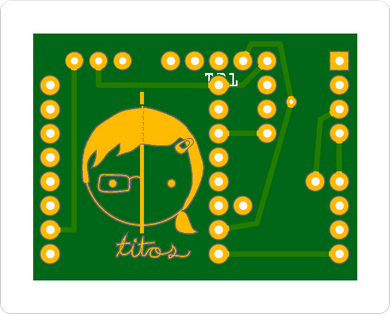
How about this for a bonus.
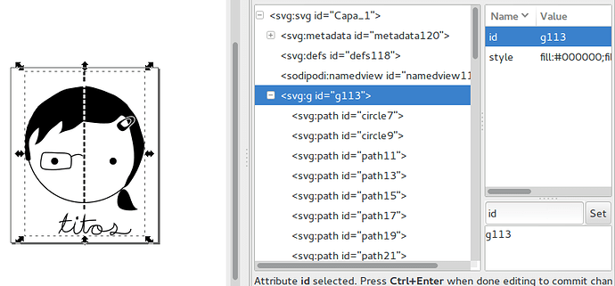
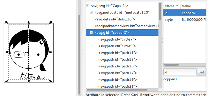
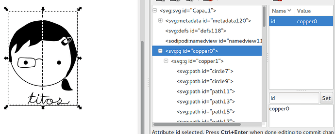
I took your picture and changed the id of the group from g113 to copper1 for the bottom layer or copper0 for the top layer. Or you can put copper1 inside of a group called copper 0 and it will work for both layers.
I then resized your image to 12.7mm wide as that was the size of the picture on the pcb and saved it as a plain svg.
After that I opened one of my existing bare copper parts based on a test point in the Fritzing parts editor and changed the images to this new image and assigned the right eye as the connection point (you have to hold down shift and scroll over the eye after clicking assign pin to choice the eye which is below the other parts of the image). Then it was just changing the meta data and saving as a new part. I then export the part for you. If you want to make other ones just change the svg in the parts editor.
Then you place the part on your sketch (you may need to disable align to grid in the view menu to get it where you want it). If you have the pcb made by Aisler you will get gold a gold plated image.

Edit the image appears to be reversed. I will update this post when I figure out why.
@segfault
EDIT 2: I figured out why it was reversed. copper0 is the top layer and copper1 in the bottom layer and if copper1 is inside copper0 it is universal. I have updated the instructions to reflect this.
EDIT 3: Here is the updated part that works for both sides.
Titos.fzpz (41.1 KB)


