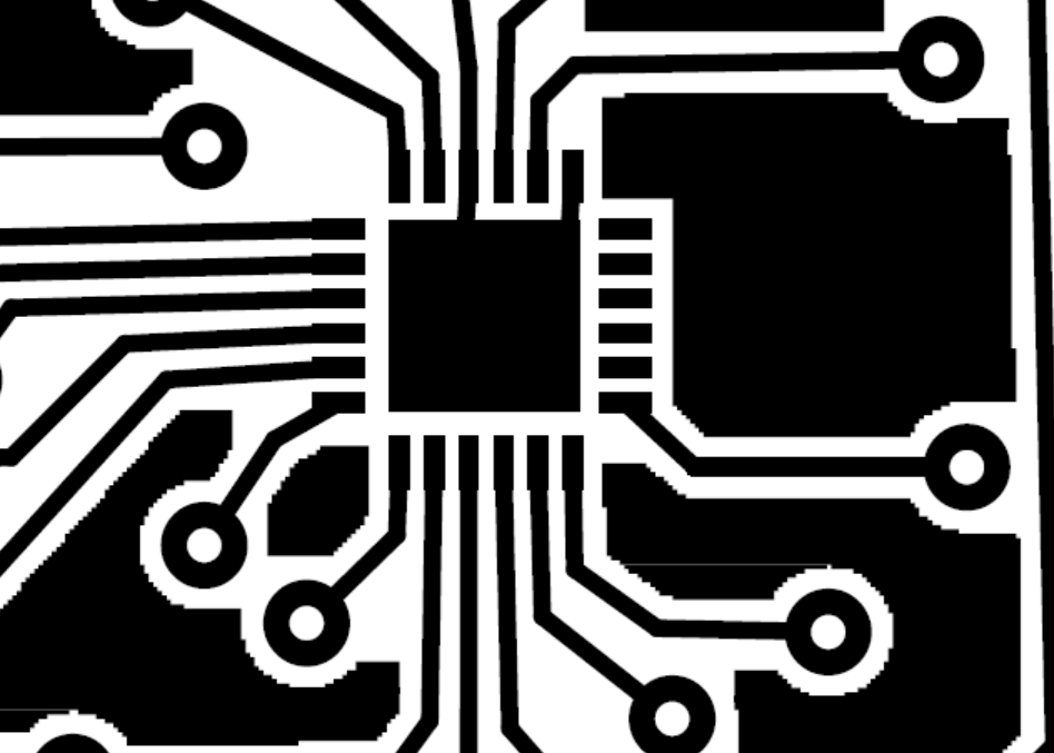
Hi Vanepp, Thanks again for the advice. I can use both methods to solder. Personally i was about to use the solder paste + heat gun method as that worked for me before with the breakout board. And for the current design, i have requested for production already , but its with a silk screen. So this should prvent any kind of solder bridges. The trickiest part to solder is definitely the QFN 24 chip. I tried to make the connections as straight as possible. I somehow missed to see the bent connections at the pads. Thats a bit upsetting for me. I have sent the PCB for manufacture which should arrive for july 13th. I hope i can give a good results 
They aren’t that far off, its just that all the distances are small and every little bit helps  . Hope this works for you.
Peter
1 Like
Will let you know Peter. You just saved my ass . I had no idea how to create parts and do graphics. If i had to move to Eagle or Altium which had this part. It would take me weeks just to know the software.
For me (after struggling with parts creation for coming up on a year with lots of help from the other folks in here ), only an hour or so with Inkscape and the data sheet. To someone new to parts creation a lot more of a problem. Once you are up to speed, parts creation isn’t bad, it just takes a lot of effort and mistakes to get up to speed. It helps a lot if you are already familiar with a svg graphics editor like Inkscape (which I wasn’t, and after a year still aren’t, it wins with regularity ) but even then fritzing has its share of things it dislikes that you need to trip over a few times
Peter.
Peter
1 Like
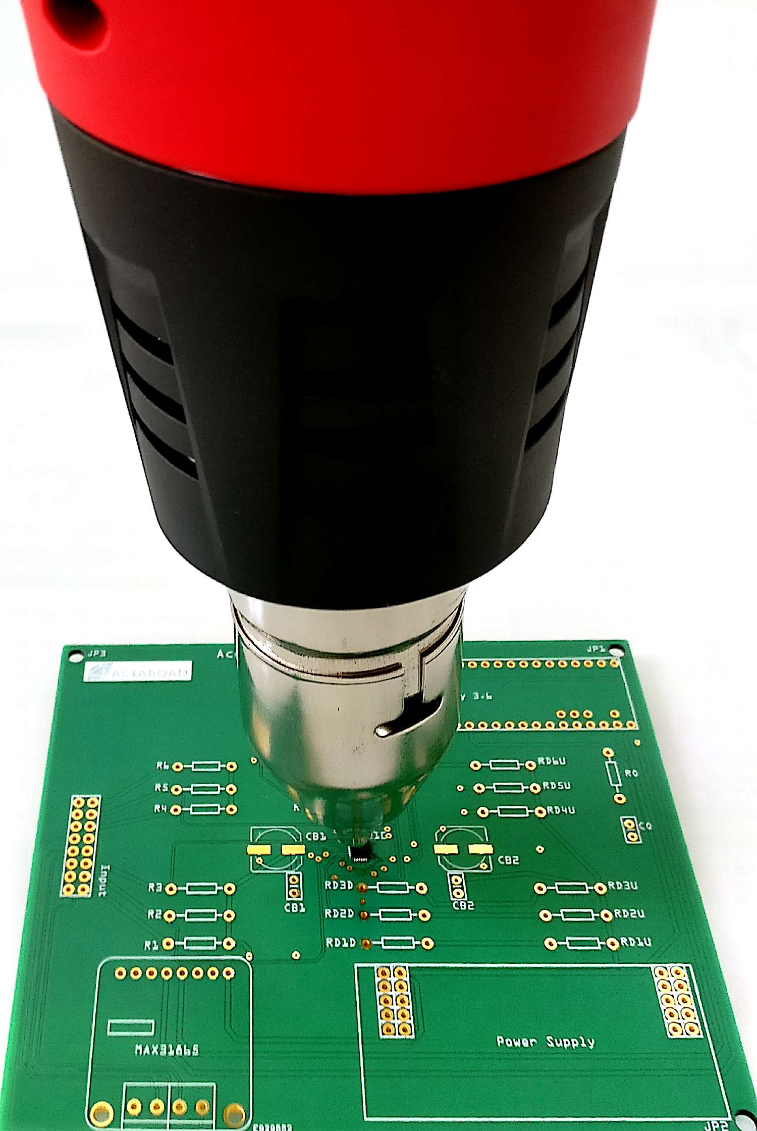
Thanks Vanepp. I should really take a look into Inkscape. Fritzing was a terrific application to built my project prototype and thanks to your help i was able to realize my PCB. Screenshot available. IT WORKED!!!, i used the solder paste+ heat gun combination to get it soldered. I have attached some pictures for your reference. It was a perfect fit. Further more, i feel like its also worth looking into other PCB softwares like Altium and EAGLE? I found it really hard to get into it. Fritzing was beautiful in that in had almost everything i needed, it was quite fun to use as well.
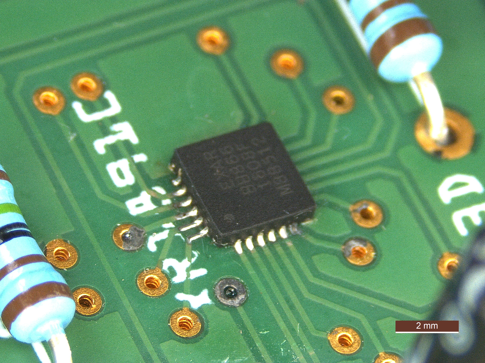
Cool. Did you have to remove some solder mask, because Van’s extra pad length made perfect fillets.
That really is cool! Glad that it worked out for you (and amazed that you managed to get it soldered so well ). Yes I quite like Fritzing more for breadboard view which suits what I usually do these days (tie prebuilt modules together) but it is by and large easy to use, although making parts takes some practice. I had tried out geda and kicad before finding Fritzing and didn’t consider eagle or other commercial products due to a previous bad experience where I bought something and it was promptly bought out and discontinued so I waned one of the open source projects.
Peter
1 Like
No i did not have to remove any solder mask. The part fit perfectly. Extra pad lengths could be a good thing i think. Short ones would make it harder to solder. But all in all, it seems Van’s pad length was a perfect match. im currently doing testing on my PCB now, and they all seem to be integrating with the chip just fine. Vanepp is a life saver.
It’s all thanks to you really. i would have been behind couple weeks if i had to redesign the PCB in EAGLE/ALTIUM or try to design the footprint from inkscape, as i would have to learn it from scratch. But i see now, that its definitely required to know some graphics editting tool such as inkscape for my work.
As for the soldering, i was quite surprised to as how to came to be decent. as the solder paste was a mess on the foot print, but i think perhaps the tining and flux played a part to it. heat gun manipulation can be tricky, if it gets too hot, then you could destroy the silk screen.
I do hope they continue to support fritzing more, one thing that is lacking is the routing feature to bend 45 degrees, this i do it manually, although it isnt too bad, but when doing it manually, sometimes it might not be as precise as we expect.
Firtzing has lots of shortcuts, like ALT from a bendpoint starts a trace, and ALT+shift does 45º
1 Like
I had no idea you could snap on 45º. I just checked and on Linux it uses the “windows” button instead of ALT. Also just simply holding SHIFT while moving a trace tries to snap to a 45º but Fritzing is unsure which side of the trace to base the angle off of.
Certainly for Frtizing Inkscape knowledge is necessary and there is a fair learning curve. For me (having been thought the learning curve at least somewhat ![]() ) the footprint was easy when it was going to be anything but easy for you. It does get easier with experience but getting the experience is painful.
) the footprint was easy when it was going to be anything but easy for you. It does get easier with experience but getting the experience is painful.
From what I’ve read, that seems to be how it is supposed to go (nice to see that it works in practice ![]() ) the flux is supposed to wick the solder it contains on to the pad which it seems to have done, although I’m still impressed with how good that looks.
) the flux is supposed to wick the solder it contains on to the pad which it seems to have done, although I’m still impressed with how good that looks.
They in this case is likely us. Fritzing started out (and got to where it is I think) as a funded research project. As such it has a solid underlying design (if with a few bugs in the implementation), when the research grant ran out, it became an open source project and I think the original developers have mostly had to fight for new research funding and then work in those projects which is leaving little time to develop Fritzing further, so now it becomes up to us to grab the source and try and fix bugs and extend it if we can. To that end I have a development environment up and am poking at the bugs that have bit me, but this too is going to have a big learning curve I expect. I can see where and why the most annoying bug (Fritzing hangs when fed a bad part) occurs, but how to fix it is so far less obvious.
Peter
1 Like
If you want to learn Fritzing and Inkscape in one hit - it’s quicker - here is a video series. There video series might seem long, but it’s a lot quicker than fumbling around. It took me a year of fumbling around, because there was no one to help back then - you can see my non-replied posts -, so 3 hours is orders of magnitude faster than what I had to do.
1 Like
Ive read about this. Unfortunately for some reason for me, whenever i ALT+shift, it produces 90 degree bends instead of 45.
With the limited time resource i have. I will see what i can do in order to pitch in and help the community. ![]()
Thank you, although it was mostly a fluke really, i have not much experience soldering SMD type components of such size.
A noble endeavour indeed ![]() i will try to stick around and help as much as i can. I can see the bug about feeding a bad part could hang. It has hung on me quite a while. Also, i notice that the the software would run painfully slow when the gridsize is more dense. I think this seems to be more of system limitations. but weirdly i dont notice the sluggish response when changing the grid size in altium. perhaps, it could use a bit of optimization there. just a thought. But seeing that fritzing is not funded anymore, it would be a definitely challenging to set time resources to work on it.
i will try to stick around and help as much as i can. I can see the bug about feeding a bad part could hang. It has hung on me quite a while. Also, i notice that the the software would run painfully slow when the gridsize is more dense. I think this seems to be more of system limitations. but weirdly i dont notice the sluggish response when changing the grid size in altium. perhaps, it could use a bit of optimization there. just a thought. But seeing that fritzing is not funded anymore, it would be a definitely challenging to set time resources to work on it.
Thanks. Subbed . Will look into it
yeah cool, i don’t know that alt forks a new trace from the bend point
but by starting from a bend point and connect to some pads, it moves the bend point a bit
and vise versa , a trave connecting to a bend point moves the bend point a bit
Fritzing is like that.
When ever you make a connect it loses the snap so you have to grab it and snap it back. This is also a good way to check if it’s connected because when you move the bendpoint back you can check that all traces move with it.
You have demonstrated your capabilities with the SMD QFN-24 part.
I think you are at the point, fieryfire, to move from THT resistors, to SMD resistors.
It turns out that smd “1206” pads are fairly close to size of THT pads, so really not difficult to hand solder.
And if you have a few SMD parts, and order a solder-paste mask, … it reduces the assembly time to have as many parts as possible SMD. Plus, SMD parts are considerably less expensive, of course.
I have found that it totally tightens the board up, from a design standpoint.
This month I moved to SMD 1206 parts. After a few boards, and a little practice, I will move to the next size down 0805 parts.
-allan
Thank you allanschwartz, yes looks like that seems to be the case i am planning to use the SMD components for my next design with the XR18910, i like excited to see how much more compact the design would go to on the other hand, if you have any experience with bridge amplifiers such as XR18910 do let me know. I think i have power supply which causes voltage fluctuations so i play to add an LDO, and perhaps 50/60Hz IC filters before the amplificiation stage of the strain bridges. im not sure if this is the best idea.