OK I’ll do that. I’m just finishing moving the right hand to also be 25mm wide and the boards should be done other than mounting holes.
That would be excellent, the more people checking the better. It is easy to gloss over an error when you have been looking at a board for a long time.
The trade off here is strength versus size. Larger gauges are stronger but larger and usually stiffer. 28 Gauge is probably too small I would recommend either 24 gauge (common but some what larger) or 26 gauge. Also stranded wire rather than solid as it needs to be flexible in this application. Different colors are also useful to make the wires easy to tell apart.
Thanks Peter for this information! I need multi-stranded flexible wire? How exactly before I order! I have a hard time choosing ! Can you give me an example and also for the dupont clip; Thank you philippe
PS: Do you live in Germany or in the United States? what time is it ?
I.m not sure dupont connectors will crimp on 30 GA, I think the minimum may be 28 ga. In this instance you want a strong crimp as it will be moving around. You would be best with 24 or 26 GA wire I think.
I also think it needs a bigger section and I will definitely do a crimp weld as I saw it on you tube: https://www.youtube.com/watch?v=iTpK3GX3RvY, there must it be good! and the spit in the Mega too I hope!
OK here are both boards reduced to 25mm wide, With the mounting holes on the dupont connector set to 48mm center to center (it was some odd fraction, and even number will make making covers easier). On the left hand one U8 is increased by 1mm. The left hand needs mounting holes and then you should be good to go.
thank you Peter
I will watch tomorrow I have no time ! and good evening good day more precisely ! and see you tomorrow thank you for everything philippe
I annotated the sketches with the logiciel " paint " to reveal more holes and especially the holes of the ends which will be drilled to different measures according to my constraints of installations. I will be away tonight and will not be watching until tomorrow morning.
I have several questions to ask you! :
1 Can you complete the arduino page with the mega card 2560 and with the pressure sensor BMP 180, the push buttons or can be a small calculator, a screen ???
2 Is the capacitor necessary?
3 I would like to put the arduino card outside in a box provided for this to have at my disposal the usb connection and power mega card 2560? would be inside the bellows only the pressure sensor?
4 To make my cables with terminal connectors dupont it would not be better terminal connectors with a single pin. ? I could more easily handle them and if one day they break I can more easily change them what do you think?
Good I stop my questions !!!
Good alarm clock and good day to you!
regards
philippe
I willl add holes at the approximate positions indicated and you can correct them if they are not in the right place.
Yes I can make a new sketch for the arduino, the pressure sensor and the buttons with the connectors to the boards from the arduino indicated. I’m not sure what a “or can be a small calculator, a screen” is.
Probably not, but you are a long way from the supply and a bypass capacitor is wise. With the pads on the board you don’t have to mount one to start with but if you have problems later you have the space to mount one. If you don’t install the capacitor you also don’t need the ground wire which reduces the wire count by 1.
That should work fine. The pressure sensor is I2C (i.e. the output is digital not analog) so having the mega some distance away shouldn’t be a problem.
The trade off here is reliability. With multi pin headers you can bolt a plastic plate on top of the connectors to hold them in position. With individual connections I expect that will be more difficult. The connectors in the accordian will be moving around and will likely tend to come loose and disconnect if not secured down. That said. which ever way works best for you is fine, individual connections will work the same way as muilti unit ones and you can change one to the other later if needed.
edit:
OK, the next set, first a new one with the mega, barometer and switches schematic only:
edit: I replaced this with one that also has the midi connector installed (although I think it needs a ground somewhere to function) which I missed before.
hello peter, here I tried to directly correct the sketches. I added1mm ( 361 mm ) pour une main seulement and put rules on the sketches. I still have so much trouble fixing the circuit boards inside the accordion, the holes at the ends are pretty random I wonder if I will not remove them from the sketch and predict them later by piercing the circuit me even . Good I think it’s good!
I send you the two sketches.
Tomorrow I will make impressions of both circuits.
Good day thank you for the sketch arduino
philippe.
While you can do this, it may be cheaper to do it here. When the boards are made if you drill a hole wrong, it is wrong, you can’t take it back out again. Doing it in the sketch and printing the sketch until l the paper version is correct insures that the hole in the board will be exactly where it should be. I expect it is frustrating to try and adjust the sketch but I think the work will be worth it in the end, but it is up to you. The sketches should be ready to produce gerber files and send them in to get a quote and see how much the boards will cost if you are happy with the sensor placement and the holes. We should both compare the boards to the original schematic to make sure all the connections and pin numbers are correct first though.
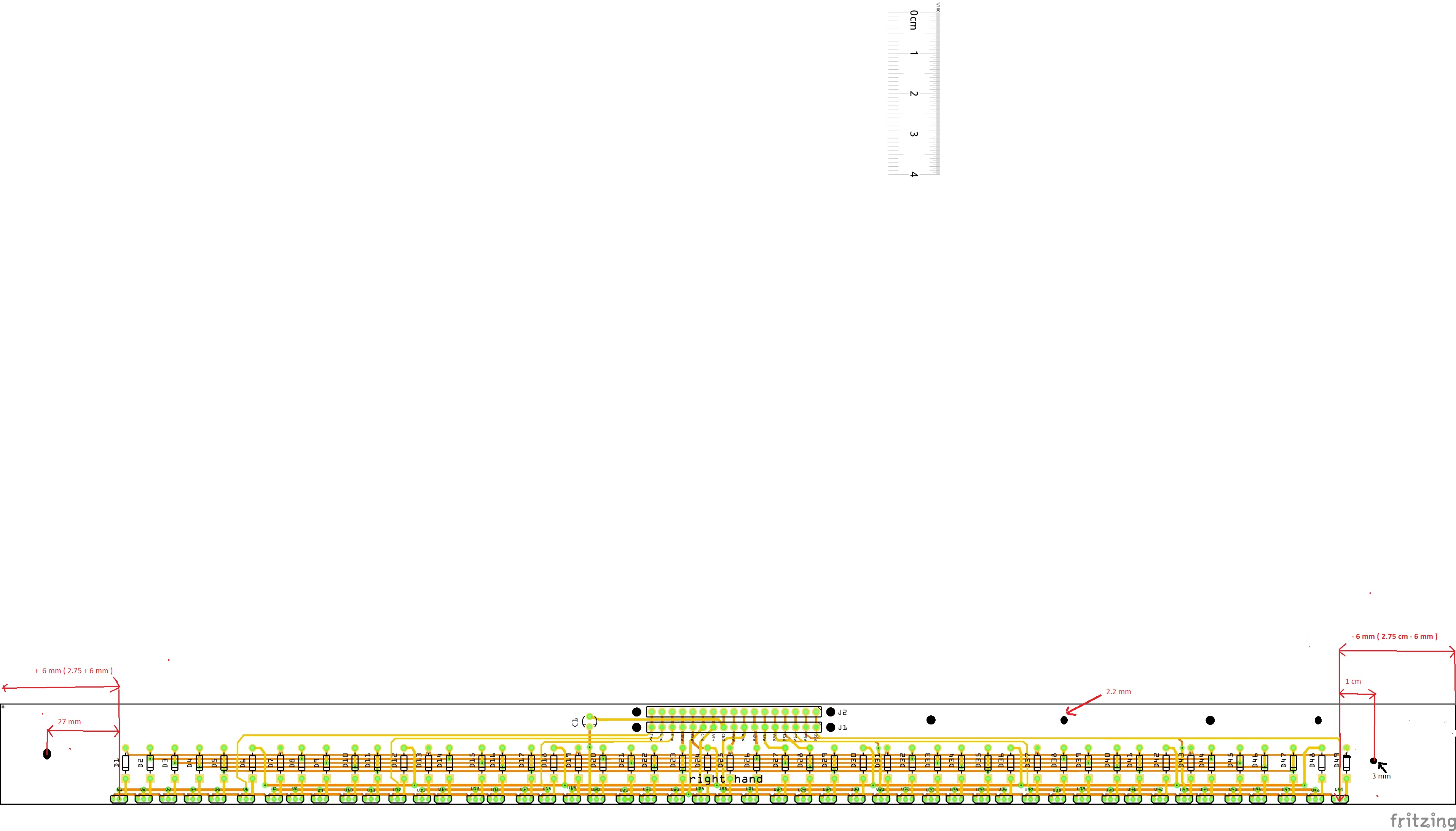
hello peter, this morning french hour (10 hrs), I have controlled the tracks of the two circuits. everything looks good and connected following the recommendations of Tom Scarff. A small remarque on the diodes of the right hand numbered from D1 to D49 and tom scarff numbers from D 50 to D 98. It does not matter !
A little more important question! Will the circuits include the markings? : J1 / J2, P41 P43, GND, U1, D1, D49 exct…
I will now print the two circuits and really think exactly how to fixed the two circuits and make my four brackets of aluminum brackets; It’s quite complex but hey I’ll get there thanks for all
philippe
good evening peter, I concentrated on the left hand by making brackets. I reduced the board to 355 mm and I repositioned the U 24 by removing 1 mm (- 1mm). I positioned the holes of the extremities and made the two supports in aluminum. Tomorrow I will try to devote some time for the right hand. Information: I will be holydays the next week from Monday 25/03 to 1/04 .I will recontacterai after. thank you for your very valuable help for my project. philippe
Sorry for the late reply I’ve been tied up all day.
It is an easy change to make if you like. It is just retyping the numbers.
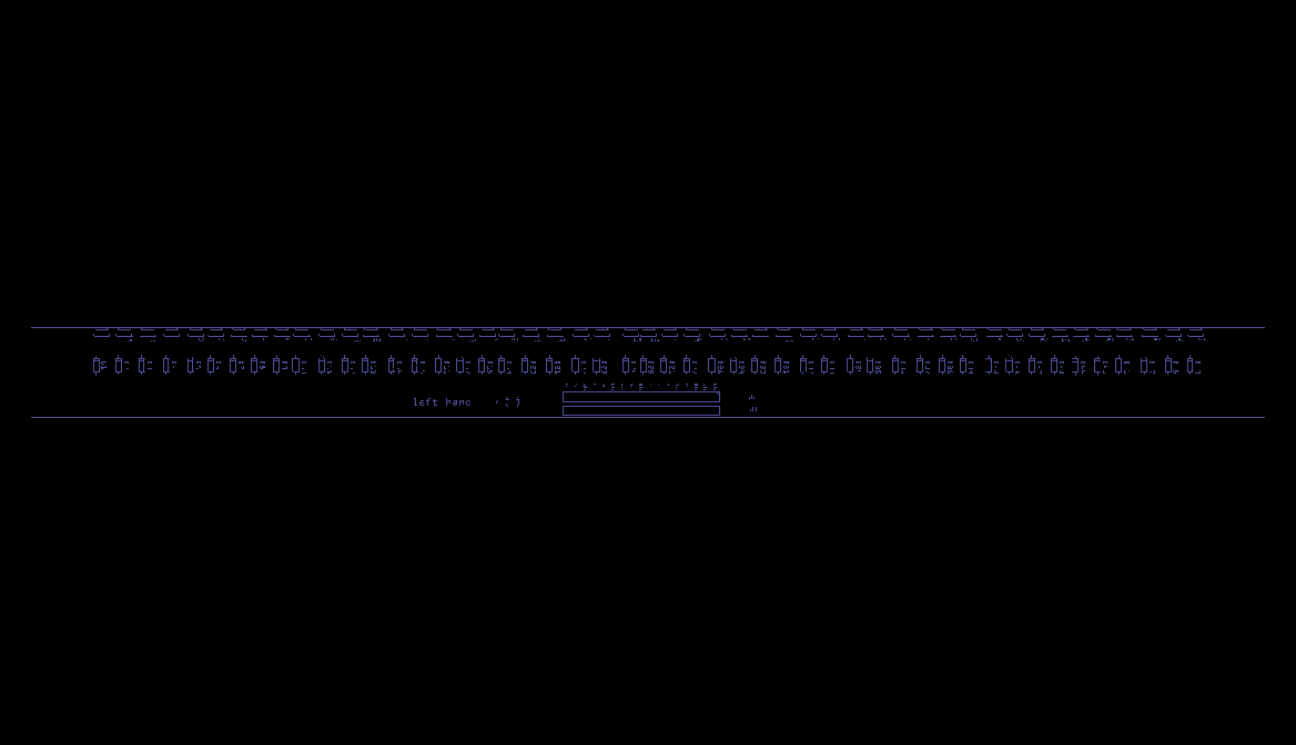
Yes, they are usually in white lettering on the top of the board. Here is what the left hand board will look like (this is likely an older copy) except the lettering will usually be in white rather than purple as here. That depends on the the board house though.
Not a problem, I’ll hopefully still be here when you get back and you are most welcome, making parts and boards is usually successful, trying to restart Fritzing development is being a lot less successful .
Hello peter, I returned from holydays, I resume my project. I have 2 questions?
I have very long (15 meters) of internet cable that are 8 strands 26AWG, I think it would be good for my assembly inside the accordion with pins dupont 7 pin and 10 pin, that do you think?
Another question, the 7 pins and 10 pins housing exist only for female pins, or also for male pins?
This afternoon I finished my bindings in aluminum and I edit the two circuit boards. See you soon philippe
thank you for your reply
As long as it is flexible enough to fit it should be fine.
The headers will take either male or female pins so you can make either gender with the same header or mixed (although there normally isn’t a reason to do that).
Thank you for your reponse, yerterday, I could not work on my project. Tomorrow I will have little time to advance on the second sketch. Normally there is no gap. I ordered the clamp, the pins and the connectors for the dupont wires and pins. Next week it should be calmer to finalize the project. Good day philippe
hello peter,
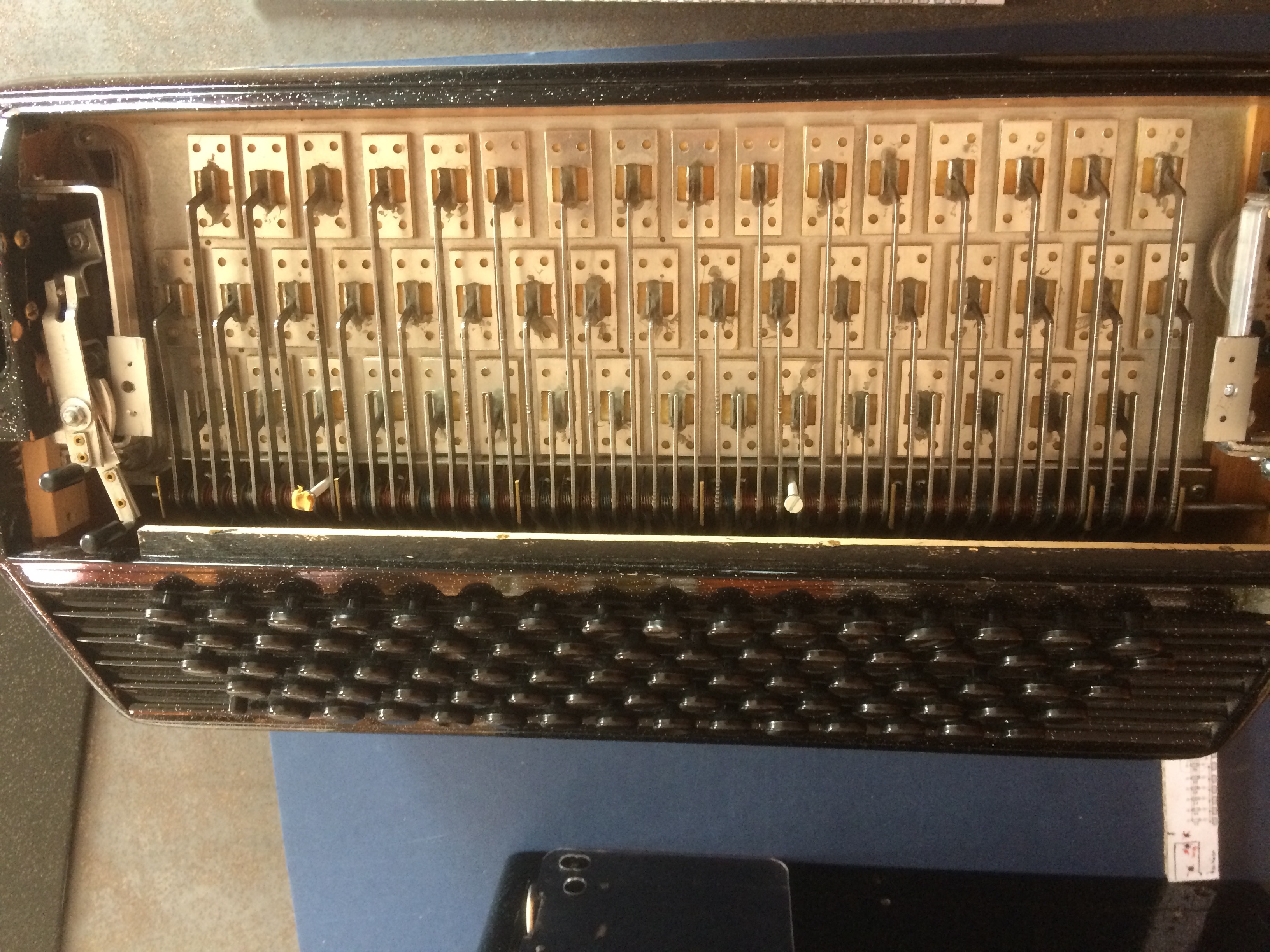
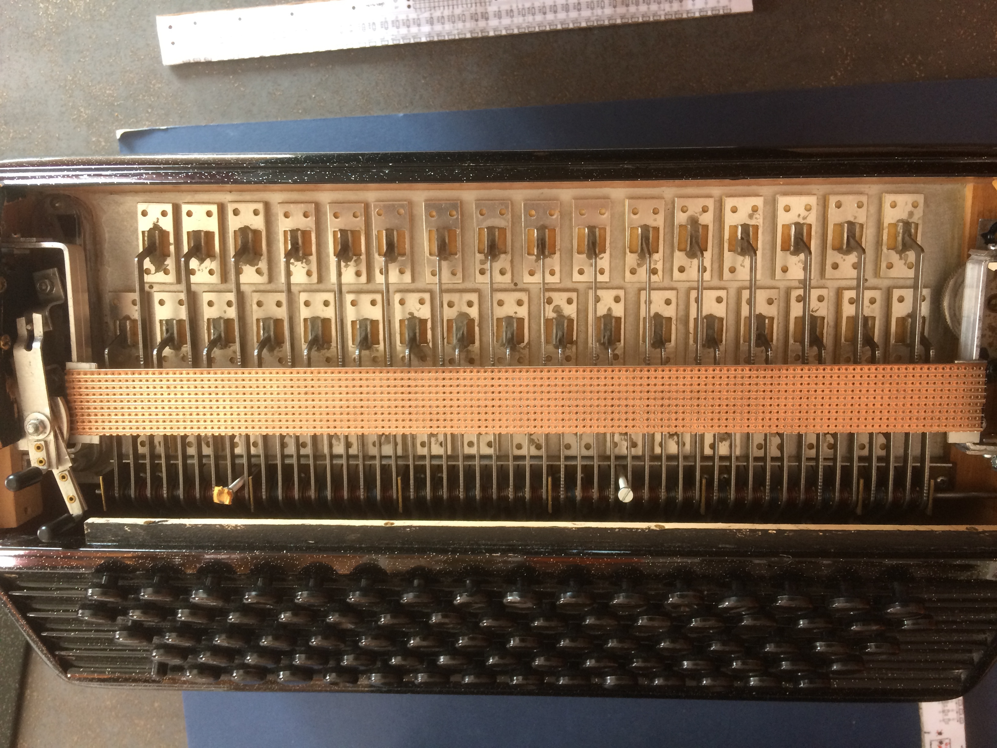
I positioned the two fasteners and made the holes at the ends for the printed circuit of the left hand. I reduced the board to 331 mm because I have many mechanical obstacles, stems of the registrations, … It is more prudent not to pierce the circuit at the ends, I will then realize at the reception with a paper matrix that I made on which I spotted my 2 holes. I made you some pictures (3). Tomorrow I look at the right hand I fix my two legs in aluminum, I realize my matrix paper and I recontrôle my sketch. But normally it should be good except maybe the total length after adjustment on the final fixings. Thanks for your help .
The mechanical fitting is often the most difficult part of a project like this. It is easy for either you or I to adjust the size and placement of the mounting holes and sensors while it is still just a Fritzing sketch. Changing produced boards is more difficult, so I agree careful consideration now is valuable and trying it out with perf board to make sure the images will work in real life is also an excellent idea. It looks like things are going well.