Do you know what company makes this part and where we can get a data sheet or where we can buy the part (because they may have a datasheet online)? Indeed I can’t find any reference online to a 735 or 735s hall effect sensor and without a data sheet we don’t know how big a hole size for the leads it needs nor what the pinout is to change the board. I am almost finished routing the right hand pcb, but need to do some work on another project for a while. If you change to these sensors you would need to test them (probably with the breadboard type setup) to make sure they work the same as the ones you have.
it is not possible to get the data sheet because the MIDI interface is made in Italy and all components are sent to France to be installed in the accordion factory maugein. Anyway I keep my sensors and I will install my sensors on the printed circuit boards. I found a solution to fix the magnets is the main one and I have a little margin to move them. It was really the big problem that I had not analyzed enough! I will use plastic dowels with a diameter of 4 mm (see my picture) I must find exactly the same dowels. I will use if necessary dupont connectors to extend my legs on some sensors but I do not think so. Mr Tom scarff sent me today the source code (INO source file) of my Arduino card. We’ll see what we can do for that it’s not important for now. Good thank you in any case for your work! Take care of your other project and if you have the time send me the project of the right hand if possible. I think that should be good for the left hand too. Thanks again for your cooperation
philippe
Hopefully I’ll be able to get back to your pcb fairly quickly. I’m helping someone else get a part fixed which has been going on for a couple of weeks now, and have some new information so we can make progress.
Ok Peter no problem
Here at the scale the representation of the two printed circuits is almost identical and perhaps the hole.thé Data Sheet for the magnets is in pdf sorry
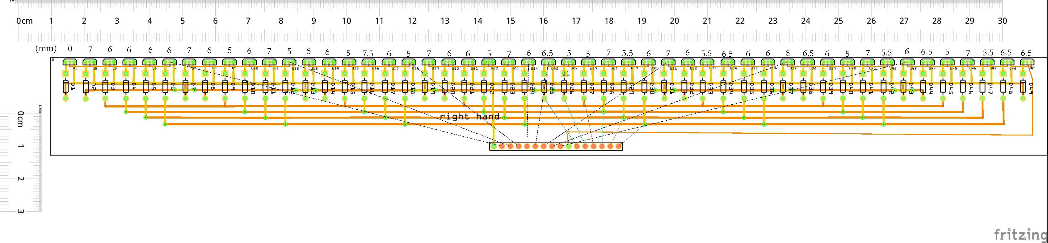
I’ve just been working on your board as a matter of fact, The other project requires me to manually translate Eagle coords in to Inkscape ant it get tiring fast, so I put some time in to finishing the routing. At this point there are only the connections left to route but space is getting tight. Here is the board as it stands now
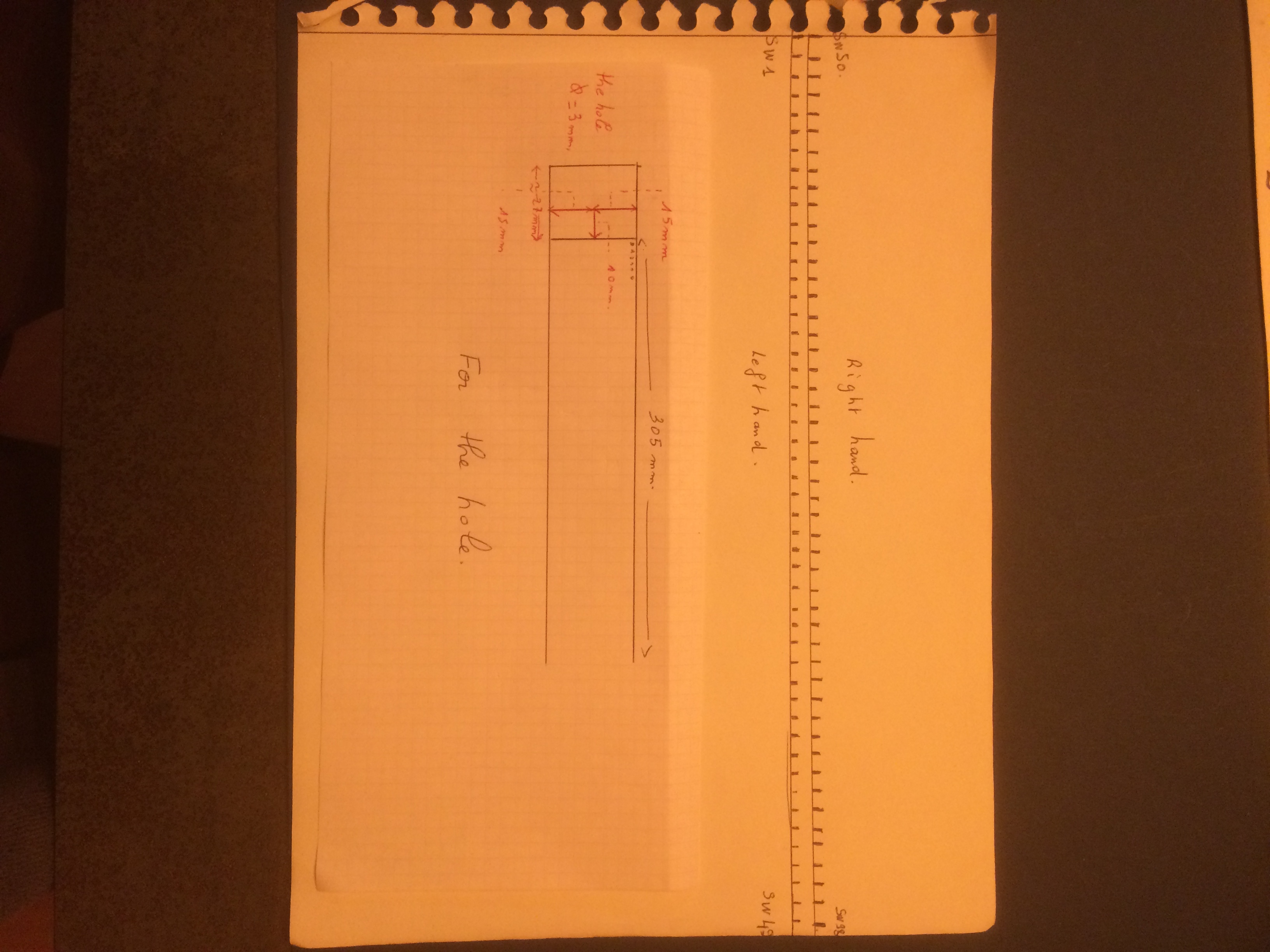
However, I have some remarks. For the circuit of the right hand I have on my sketch 304/305 mm taking the rod or the pin 2 (gnd) as axis and your sketch gives 292 mm of the pin 2 (gnd) D1, to the pin 2 (gnd) D49. I use your ruler to measure. For the right hand the rod 50 is not used, there is no sensor therefore, there is no magnet, there is no circuit! It’s a question !
My measurements are a little random maybe! ( 1/2 mm ) thank you philippe
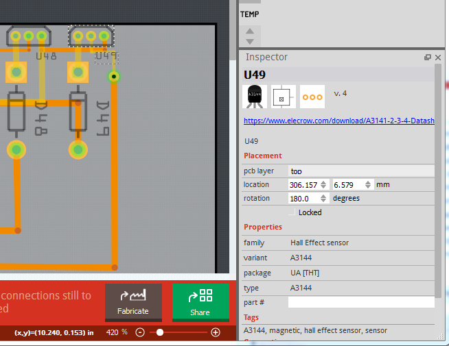
Yes that is correct, at present the end to end spacing is 291.873mm from U1 to U49. Rather than use the rulers (which I am using to keep the traces level rather than to measure anything), I selected U49 and read the position from the Inspector window, as shown a few posts back. Subtracting the U49 X coordinate in mm from the U1 X coordinate gives the exact distance between the two. However the positions of the sensors are not fixed, nor is the size of the board, both are changeable in Inspector. I have discovered a routing problem and need to rearrange the traces to fix it. I’d suggest that you us e Inspector to move the sensors to where you need them (I could do this, but I don’t know where they should move to to make placement of the magnets easiest). To help with that I have increased the width of the board outline to 310CM in Inspector to give you room to move the sensors in. Now using Inspector you can move the sensors (one at a time unfortunately) to where they best suit you. The traces will follow but will need to be repositioned once all the sensors are in the right place. This picture is the current board before changes. Note that Inspector is showing U49 the last sensor, that is what it will move.
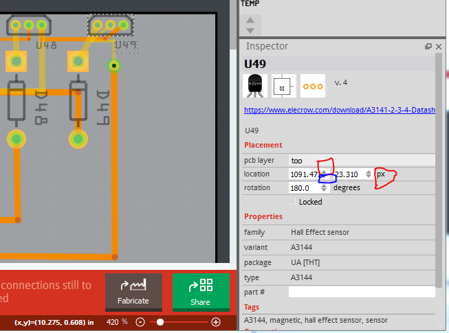
To move the sensor I changed the units to px (1/90 of an inch) and used the up and down arrows (circled in red and blue) to do the actual move (only in X) to move the sensor. You can type numbers in to the position field but the arrows (which move a small number of units per click) are usually easier. If you move all the sensors to where they are best positioned for your magnets and then save the sketch and post it here I can move the traces to make the board correct with the sensors in their new positions. Here sensor U49 has moved to the right a bit, the traces are in the wrong position but that is correctable later:
Good evening Peter,
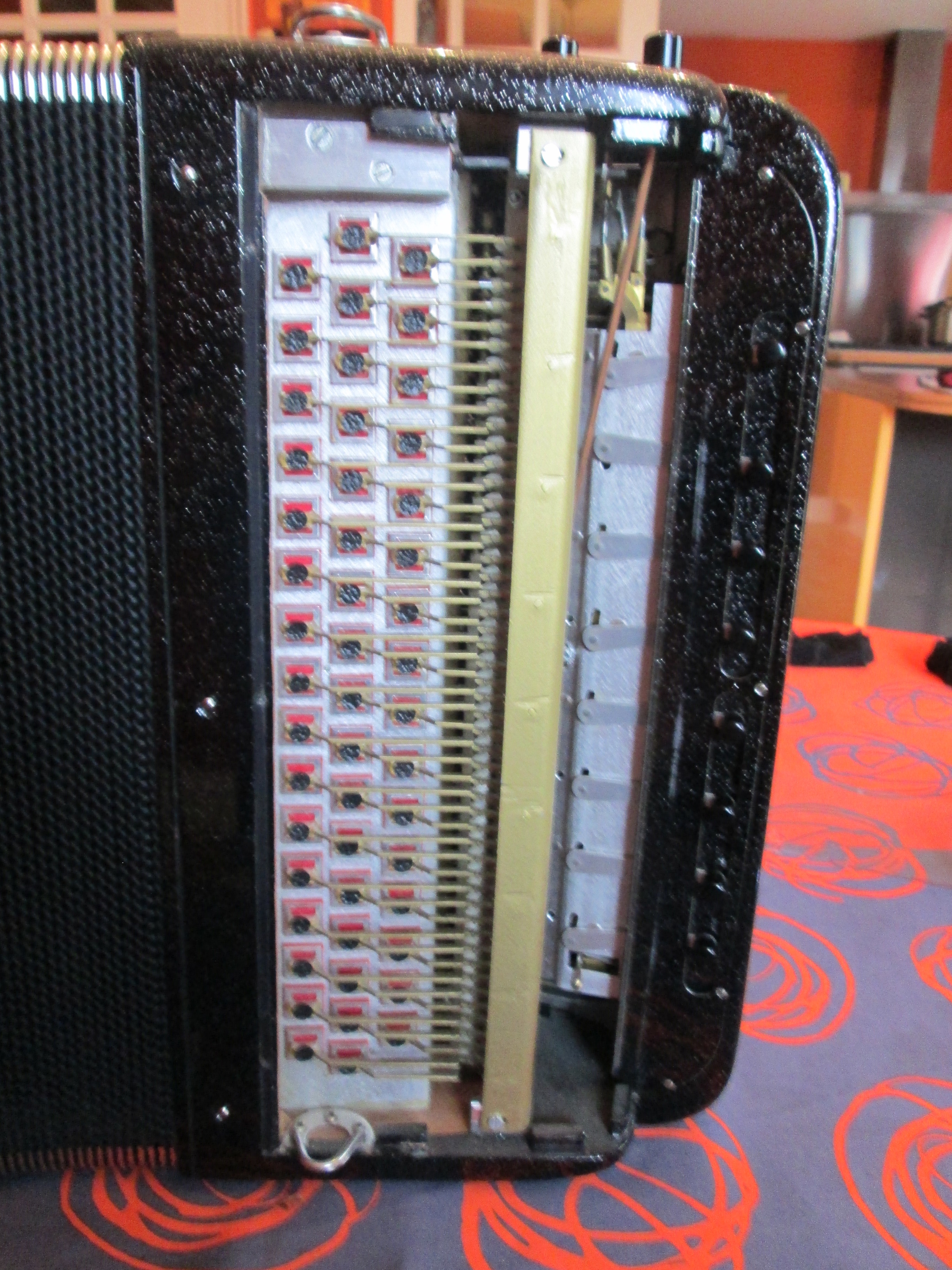
Difficult for me to make changes on your sketch! I think what’s important is whether all the hall sensors are aligned on the PCB as shown in your sketch. Each magnet will be glued and fixed to a 2 mm (valve) rod after the PCB has been put in place and will be aligned under the corresponding sensor. I will edit a photo to show you. I thought that the 49 sensors can not fit on the same track because of the spacing of the solder holes at 2.54 mm? I can not do anything tonight.
Can you make me a sketch at scale 1 ?
Tomorrow I am changing a photo to explain.
Thanks to you philippe
The 2.54 mm spacing requirement only applies to perfboard (which is fixed on .1 in centers). Boards can be any spacing that works (traces can’t be too close together is pretty much the only rule), so I can put sensors on any grid I like (6.1 mm between sensors in this case). Why is it difficult for you to change the sketch? Fritzing is designed to be easy to use, you can’t damage anything by making changes, you can keep a copy of the original file and make a new one to experiment on. My thought is that if moving the position of the sensors on the board makes placement easier then you should do it (I don’t have the device at hand to see how to space the sensors but you do). The image in pcb view is exactly how the finished board will look. As to a scaled drawing, you can print the pcb layout on a laser or inkjet printer at 1 to 1 scale. I’d suggest using overhead projector transparencies so you can see where the pads are when overlaid where the board will go. If you use standard paper you could in fact insert or glue the sensors to the paper to see how they will be aligned when soldered to the real board (glue the paper to cardboard if necessary to make it stiff enough). Before the boards are made, changes are easy and inexpensive (except in your time) That way you can see exactly how the board will look and move the sensors and try again if a move would make alignment easier. I think that if you can figure out how to move the senors in Fritzing you should be able to make a board where the sensors can be soldered in straight and not need to be bent to align with the magnets.
Hello peter. I actually understood how you realize the points of contact on printed circuits. last night I was also planning to make a copy of your version of the fzz file. the idea of printing on a transparency is good, that of cardboard also more practical.
I also have an idea to submit to you for the printed circuit of the right hand ???, I have another location that I can can be considered it has advantages and possibilities of connection and some inconvenient drawbacks (see photo attached here) ). I’m going to make a photo, with comments and also the ribs, the spacing of the rods is I think very well. I check all this and I contact you in the meanwhile thank you for your collaboration on this project is very informative and exciting. philippe
At the end of the day I will look more precisely how to move the sensors, I will also look a little how you have arranged the sketch in more detail. I have a question why your first image is in “mm” and the second in inch how do you go to systematically with a display in mm? It’s very good your job ! thank you for all
Fritzing will display most things in the units you choose (inches, mm or px). If you change the display units it just recalculates the values. I usually use inches (because I’m old ) but in this case have usually been using mm because you are and sometimes px to get fine control of position. I think I have managed to finish the other project (although there are a few parts requests I may work on for a bit), so I should be able to get back to finishing the routing on this soon.
Good evening peter, that’s what I did at first. I spotted the spacing of each sensor taking pin 2 gnd and this reférence as an axis. I used my rule. Tomorrow I will try to modify your sketch. Good evening philippe
good evening peter I do not understand why I can not change the coordinates of the sensors correctly. some decimal places are changed after incrementation! it is a user-friendly software but not easy for a beginner …
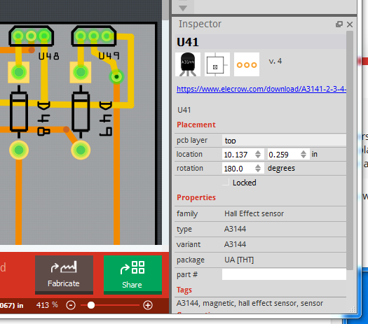
I agree, while Fritzing is a lot easier to use that the other EDA programs it is still fairly complex. I think the most likely problem you are having is selection (correct me if I am wrong here). In order to change the position of something you must have it selected which isn’t always the easiest thing to do (because Fritzing sometimes selects something other than what you expect). Assuming you want to change U49 (the end sensor), first you need to select it so Inspector recognizes it. Here is an image with U41 (off screen) selected and thus U49 not selected:
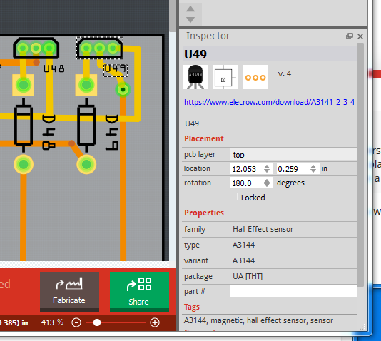
U49 looks just like U48 next to it and Inspector says “U41” to indicate U41 is selected. To select U49 you need to click on it til it looks like this and comes up in Inspector as U49:
Notice the dashed line around U49, that is the selected indication (It could also select one of the traces nearby, in which case that would have the dotted line around it), as well Inspector now shows U49 is selected. At this point you can either type numbers over the X and y coordinate values, or use the up and down arrow beside the numbers to increment them and thus move the part. You likely only want to move in X (horizontally) so you want the left most box in location.
Hello peter,
I understand how to select a U49 component for example, I sufficiently magnified the view is I click that it’s not difficult then I know very well select the sensor is change the values in mm however the software changes the value that I have worn! after moving to another component example U 47 I do not understand why !. I annotated the file fzz with my values in mm between each sensor taking as axis the pin 2 of each sensor and knowing that the magnet will straddle the corresponding rod in the same axis. I am going to install iphotodraw for you put more specific informations. thank you
Ah! Easy to fix. You are likely being bit by snap to grid (which is enabled by default). Click View, then untick Align to grid (4th icon down).That should fix the problem. I have the grid size set to .1 mm (instead of the default 2.54mm) which will do the same thing as disabling snap to grid. I’m just adding a second connector to deal with the two connections to 1 mega pin and will post the fully routed boards for both sides.
Yes, something odd there, with all the grid stuff off, mine is still snapping to a grid of some kind (or is just plain wrong). Looks like a Fritzing bug. It may be round off error in floating point, although mine is off further than yours seems to be. For me setting 21.275 changes to 21.257 I can get closer by moving to px, but this isn’t right. In the big picture though, it is close enough I expect, we won’t notice .02 mm difference (as long as it doesn’t accumulate across the board which it should not).
Edit:
OK here are two sketches with complete boards for left hand and right hand. Major changes: double the connectors so you can connect 2 wires to either board for the shared wires from the mega, added a ground and a bypass capacitor (may not be needed but available if it is), tightened up the routing to make space for the second connector. It would be best if you switched to the left hand sketch to make your changes, but since they are currently identical it shouldn’t matter. Technically these two boards will work as is, but the routing is only rough (although correct) as it will change if the sensors move.
new left hand board (the same as the right with pin numbers changed at present):