Hello… Why my breadboard connection is complete but my schematic connection is not complete?? The schematic connection shows that 1 connection still to be routed… But my breadboard connection shows routing completed… Anyone can help me?
Thank you…
Hello… Why my breadboard connection is complete but my schematic connection is not complete?? The schematic connection shows that 1 connection still to be routed… But my breadboard connection shows routing completed… Anyone can help me?
Thank you…
The most likely answer is that one of your schematic connections isn’t connected (if you click on each connection, all the rest of the points it is connected to should light up, if one doesn’t that is likely the connection that needs work). Post the .fzz file of the sketch that doesn’t work (7th icon from the left on the reply tool bar) and one of us will have a look at what is wrong.
Peter
Circuit Diagram.fzz (44.7 KB)
this is my .fzz file
can u help me to see where is the problem?
i’ve recheck my connection but there still shows not complete…
thanks alot…
I read about this before but I can’t remember if it’s a bug or because you have traces on traces and something isn’t connected.
I can’t see any ratsnests in SCH and if you click on the “20 of 21 nets” it says there is no unrouted traces, so maybe it’s ok.
The proper way to do junctions is run a trace, grab it somewhere and move it to create a bendpoint, or right-click add bendpoint, and the hold down ALT and click on the bendpoint and make a trace to where you want to go. Afterward check a bendpoint by moving it to see if all traces follow it, but note there is a bug with 4 trace junctions where it will only move 3 traces at a time.
I’m inclined to agree with Old_Grey that this may be a bug, unfortuantaly it looks to me like it may be database corruption as pcb view shows 4 nets routed but has no traces at all (which should mean no routes). I’ll poke at it a bit and see if I can identify the problem. The usual reason for database corruption is a mismatch between breadboard and schematic. Usually a component in breadboard being the opposite orientation to the one in schematic and the connection causes a short. Even if you correct it the database tends to get confused because of the initial bad routing and the only sure solution is to remove all the routes in all views and try again. I’m currently deleting all the runs in schematic to see if that does anything to pcb and will go from there.
Peter
Peter
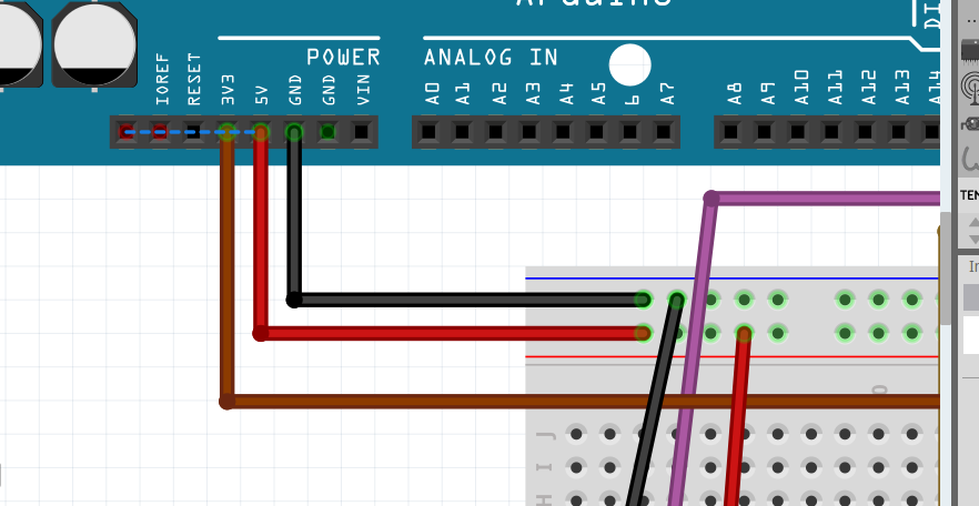
You have a few strange connections to your Arduino Mega in breadboard that need to be deleted and replaced where the ratsnest lines appear.
Good catch! It may not be easy to fix though. I deleted all connections in both breadboard and schematic and in the end had to delete the breadboard (as it has connections with no wires) to get the database properly cleared. Hopefully just redoing the wrong breadboard connections will fix it, but if not you will either need to do what I did: remove everything including deleting the breadboard to clear the database and then drag the breadboard back in again, or start again. My method at least leaves your components situated where they are now, and is what I would do. Check that all three views show routing complete (as there are no connections) with the breadboard deleted to make you got everything.
Peter
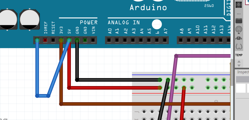
When I deleted those wires and added the new wires my sketch did show routing complete in both breadboard and schematic so I am not sure what you mean by clearing the database.
Circuit Diagram x.fzz (44.1 KB)
Sometimes the wires in error confuse the routing database and just correcting the wrong wires isn’t enough to correct routing. If he is luck that isn’t the case here, if it is the only cure I know is to delete everything and start again.
Peter
If it helps then I have often found it easier to start again - you can have your old version open to act as a reference so it doesn’t usually take too long. I’m currently on a 5th version of one of mine due to some silly mistakes I made on all previous versions, but practice hopefully improves things
Cheers,
Ben
I’ve solve my problem…
Thank you everyone for the help…
Appreciated…
Why didn’t you download the one I fixed 15 days ago?