I am wanting to build a PCB board that will include soldering in an Arduino Micro that already has male headers on all of the pins. When using the Arduino Micro from the library, I go to the PCB view and it gives the outline of the device with all the pins and holes; are these holes through hole where I can run a trace to the top or bottom of that hole and have continuity, OR do I have to select that I am mounting the board to the TOP, then run all my traces on either top or bottom?
In the photo, I have traces running on top and bottom for space reasons, does this work?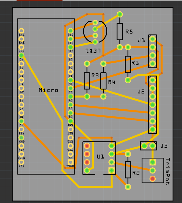
The usual procedure is that you use the Arduino on the PCB as template for the holes and position, but when you actually make the PCB you solder a header on the PCB to plug it in.
In your case you will have to dummy fit it on the table or in your mind, and judge the male pin direction as to whether it will fit to the top or bottom side of the PCB. Just look at pin numbers and see if the FZ drawing is the same. If it goes on the other side press the bottom side button on the red bar at the bottom, and drag it in and it will be flipped looking at it from the top.
Ok, I want to be able to put the Arduino on the top layer, and solder the connections on the bottom layer and run traces to the pins on top and bottom. Are those holes through holes where I can push the Arduino with existing male headers through and have continuity despite which side I run traces or solder it in?
Or does FZ only plate the connections for these Arduino headers on one side of the board?
The plating has to do with the PCB manufacturer, but even then you can solder the pin on both sides and use the pin as the link.
Go to File/Export/For Production, and you can check the drawings if actual pads and traces exist. You can check the Gerbers as to what the PCB manf will see.