Yet another Ebay special, this time a cheap small 6 wire slip ring. There have been large (40mm) expensive (>$20) slip rings available for some time which I have resisted. Then I came across these on ebay (search term “6 wire slip ring” will turn them up) for around $4. They are small (24mm) and will take up to 2A (although the wires are pretty small) and do 300rpm. They are used for rotating camera mounts usually but I can think of other uses as well such as a robot wheel with a gear motor driving the wheel, thrust bearings for mechanical strength (because these are only meant to get electricity across) and one of these to get power and direction signals to the motor /motor driver on the wheel . If you attach a shaft encoder (for position) and a steering motor (for direction) by turning the motor and wheel through the slip ring you now have an independently stearable drive motor (you need the shaft encoder to make sure they are all pointing the same direction ). Of course tilt/pan/rotate camera mounts are another use. In any case here is a Fritzing part, all three views. PCB is slightly odd in that there are only 6 pads for 12 wires, but the other 6 wires will connect to something off board and it doesn’t make sense to connect both ends to one board (it can’t rotate then which is the whole point). Complain of you see problems .
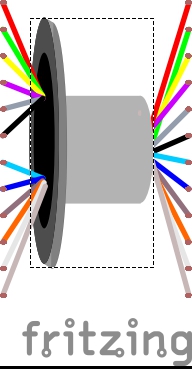
Edit: by request, a jpg of the bb view so you can see what it is:
What you see is all stationary, the 6 wires out the right end are the rotating part
encased inside the smaller tube (with no mounting holes ). I suspect gluing something on or drilling a small hole or holes to strain relief the wires would be a good bet.
These are interesting and I never knew they made premade version of these. Thanks for sharing. One suggestion would be to make it 2 parts so you could have them on separate Schematics, Breadboards and PCBs since in some sense this does connect 2 different circuits. Or if you know enough about the formatting maybe you could select which side you want in the properties?
I thought about that, but decided that the same part should do for both as there are only the 6 pads and you can connect either end of the part to them or is there a way I don’t know of to have more than one board in a single sketch? I assumed the other half of the connection would need to be in a different sketch in which case you can use the same part (remembering there really is only one not two needed).
I guess since they are wires you don’t really need any specific PCB view so that part is moot. But as far as multiple projects in a single sketch yes that is possible. This schematic has 15 boards in 15 schematic frames.
The PCB has 18 boards tabbed together and Fritzing does just fine.
My breadboard view is just stacks of overlapping parts and ratsnest lines as I don’t use it.
I mostly work backwards since I am usually making tiny packed boards that stack or piece together in some way. I have to build the boards first then complete the schematic to make sure I have a working circuit. Working from schematic to PCB can lead to impossible to route boards because of having to pre-choose the ports on the MCU etc. Sometimes I do not even know what components will fit on which boards so the schematic ends up being broken into many individual schematics.
Sure, for me (used to making parts) it is relatively trivial. Do you have a data sheet or dimensions of the 12 wire slip ring (I’ve only ever seen 6 wire ones, although I admit I haven’t looked that hard). Mostly the diameter of the inner and outer rings horizontal length of the case and the wire placement and color (assuming color coding) for breadboard view. Schematic may look a bit cluttered, it is fairly busy with just the 6 rings .
Edit: At a guess this is the adafruit one (first one that came up in google) so I’ll assume that and make a part. Hmm, a further look indicates Sparkfun has different ones again (also 12 wire) so I’ll hold off until I know which one you want since there are ones with flanges and ones without and different color schemes on the wires.
Below are a new copy of the original 6 wire (the major user visible change is that in schematic the pin order now matches breadboard and pcb rather than being opposite) and a new 12 wire part and their associated bb pictures. I used the colors from the Adafruit part (because their data sheet had colors listed ) which will probably not match the other parts but electrically they are all the same so this shouldn’t matter (I’d say you can also change them with parts editor, but it is a bendable leg part and thus part editor can’t deal with it, so it won’t be that easy.)
Then (other than the flange which yours doesn’t have) you are in luck because that’s the data sheet I used for the wire colors . With a previous part to clone, this one is reasonably trivial. Figuring out how to represent it in schematic in a reasonable way (and stealing the breadboard cylinder from someone with artistic ability) were the hardest parts of the original. By this one it’s just clone and change connector names. Luckily we have lots of examples of very fine artwork from artistic people to borrow from.
This might be a bit of a long shot, but are you able to make brushless variantssimilar to this https://powerbyproxi.com/slip-ring/? Obviously there’s some advanced tech used in ones like this, so not an exact match. just after something a little safer / more secure / with protective housing as I’m worried about the longevity / survivability of the wires given what I’m using this for, and curious if that’s something that can be done outside the bigger manufacturers? thanks!
A Fritzing part can be made for almost anything but we need a data sheet for what ever device you want to use to make the part. There don’t appear to be any products just examples of what you might do in the web page.
 ). Of course tilt/pan/rotate camera mounts are another use. In any case here is a Fritzing part, all three views. PCB is slightly odd in that there are only 6 pads for 12 wires, but the other 6 wires will connect to something off board and it doesn’t make sense to connect both ends to one board (it can’t rotate then which is the whole point). Complain of you see problems
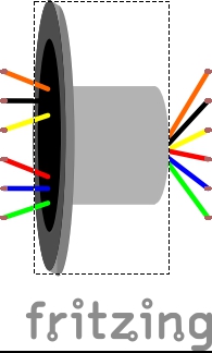
 ). I suspect gluing something on or drilling a small hole or holes to strain relief the wires would be a good bet.
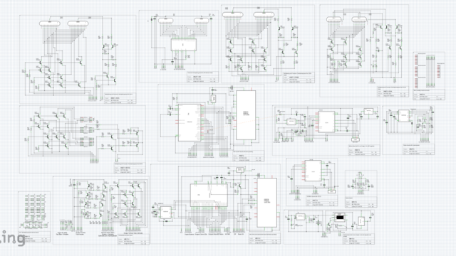
 .
.