
Nice job in breadboard, but a few problems: dimensions are in px, which can cause scaling problems (and has here):
my new part on the left has the dimensions changed from px to in. I would guess this was done in an earlier version of Inkscape such as 0.9.2.1 that is 90dpi/px where I am using 0.9.2.4 which is 96dpi/px. If dimensions were in in or mm that wouldn’t matter, but in px it does (as well Fritzing guesses at the px value and often gets it wrong.) I also chose to add connectors for the barrel jack instead of only the terminals (and suppressed them in pcb view as not useful, which turned up a new Fritzing bug!) It is possible (I did it to see a couple of years ago) to make a barrel part that will “connect” in breadboard with a female barrel socket, thus the extra connectors. Nothing I am aware of uses this, but it is possible and a wall wart using it would be useful as a part (I just haven’t gotten there yet.) In pcb
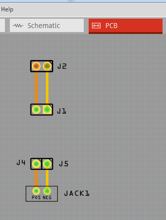
The holes in pcb are too small for a .1 connector (0.030in instead of 0.038) and the pads are paths which make it very hard to change the hole size (at least for me). I also removed the text. The reason is, if the text is in the part, you have to modify the part to remove it if you don’t want it. If the text isn’t in pcb, you can add it to the sketch if you want it, but someone that doesn’t want it doesn’t have to change the part to remove it.
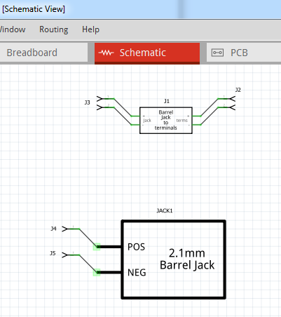
Schematic is too large (space is valuable in schematic, smaller is better) and lacks terminalIds. Because the pin is square, (which is non standard) that is less of a problem than it might be. Svg scales are incorrect, but that is a minor issue. All of these are fixed up in this improved part (breadboard needs the scale adjusted so it matches the real part though):
2.1mm Barrel Jack with Terminal Block-improved.fzpz (6.3 KB)
Peter
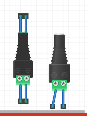
Awesome graphic!
Why does the part also have a PCB view? I own these, too, but mine only have screw terminals. There are no pins to solder them onto a PCB. Is this a different variant, or would you always add a PCB view? If I did a part for the ones I have, I would have left out the PCB view.
In this case, the intent would be to use wires from the screw terminals to connect to the pcb via the holes intended for a .1 header part (although I don’t know why you would want to do that!) Leaving out the pcb view would be another viable option. It is whatever the part maker chooses to do, as either is acceptable. It requires more experience to remove the pcb view from a part though as it isn’t well documented.
Peter